Warning, 6 electrical connection, Installation and start-up – KACO blueplanet 1502xi User Manual
Page 28
Page 30
blueplanet Operating and Installation Instructions 1502x - 2502x
Installation and Start-Up
5.6 Electrical connection
General information
The electrical connections can be established after the inverter
is installed in its fi xed location. Knockouts are provided on the
sides, bottom, and rear of the inverter bottom plate to easily
run conduit to the desired locations.
NOTE
Only conduit pipes according to UL 514 B can be used.
Guide the wiring through the conduit pipe.
!
WARNING
Inputs and output circuits of this unit are isolated
from the enclosure. System grounding must be done
in accordance with the National Electrical Code
(NEC), ANSI/NFPA 70 and is the responsibility of
the installer.
You must adhere to all mandatory safety regulations, the
currently required technical connection specifi cations of the
responsible power supply company, as well as to other gener-
ally applicable regulations.
!
WARNING
To connect the inverter, the AC and DC sides must
be disconnected from all power sources and secu-
red against being inadvertently energized.
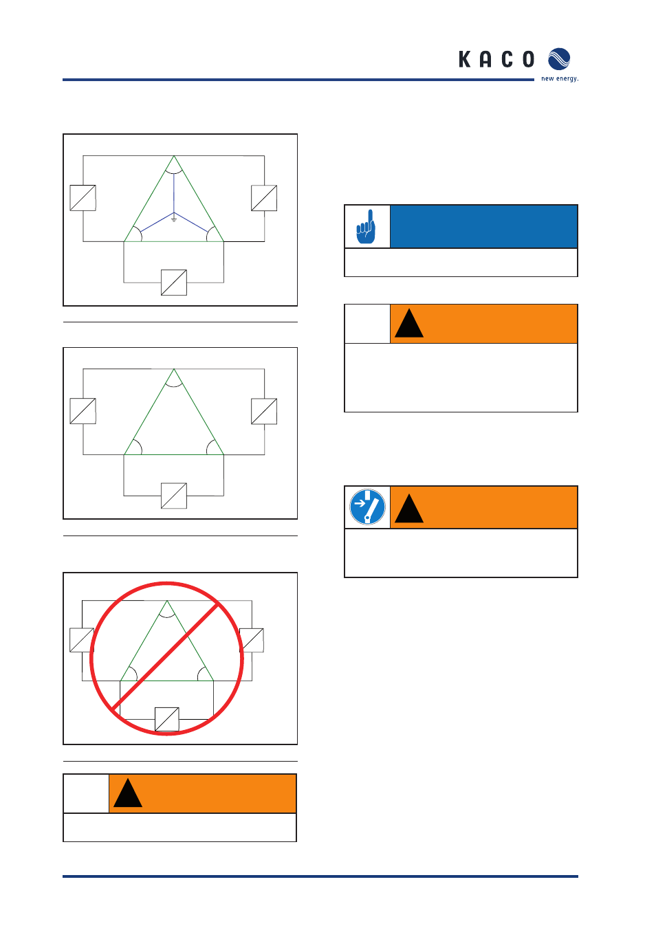
Country setting on the display: USA 240 V no neut
L1
L2
L3
120°
120°
120°
~
=
~
=
~
208V
208V
208V
120V
120V
120V
N
=
Figure 18: 208 V / 120V WYE
Country setting on the display: USA 208 V
L1
L2
L3
120°
120°
120°
~
=
~
=
~
208V
208V
208V
=
Figure 19: 208 V Delta
Country setting on the display: USA 208 V no neut
L1
L2
L3
120°
120°
120°
~
=
~
=
~
480V
480V
480V
L1
L2
L3
120°
120°
120°
=
~
480V
480V
480V
=
Figure 20: 480 V Delta or 480 / 277 V WYE
!
WARNING
Do not connect the inverter to the 480 V Delta or
480 V / 277 V WYE power grids.