Warning, Action, 5 connecting to the public grid – KACO blueplanet 1502xi User Manual
Page 27: 240v
blueplanet Operating and Installation Instructions 1502x - 2502x
Page 29
Installation and Start-Up
5.5 Connecting to the Public
Grid
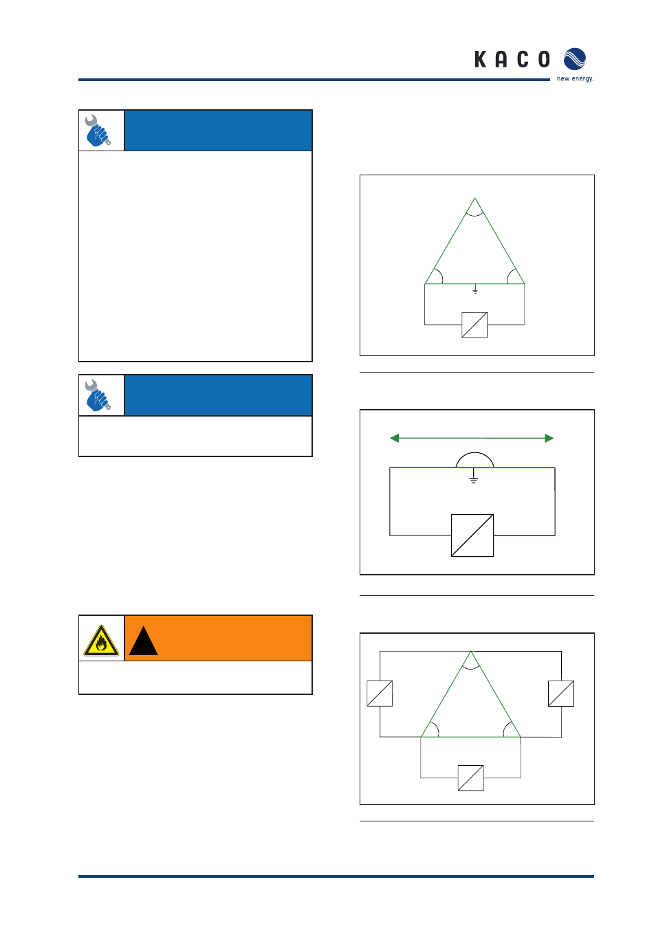
The inverter can be installed on the following grid-types:
L3
120°
L1
L2
120°
120°
=
~
240V
240V
N
120V
120V
Figure 15: 240 V Delta: 120 V Stinger
Country setting on the display: USA 240 V
240V
180°
L1
L2
=
~
120V
120V
N
Figure 16: 240/120 V Split Phase
Country setting on the display: USA 240 V
L1
L2
L3
120°
120°
120°
~
=
~
=
~
240V
240V
240V
=
Figure 17: 240 V Delta
ACTION
Before connecting the PV generator to the blueplanet, check
that the PV generator is not grounded.
– Measure the DC voltage between the protective ground
(PG) and the positive lead and between the protective
ground (PG) and the negative lead of the PV generator.
– If stable voltages can be measured, this indicates a
ground fault in the PV generator or its wiring. The ratio
between the measured voltages gives an indication as to
the location of this fault. Rectify this fault before taking
any further measurements.
– Measure the electrical resistance between the protective
ground (PG) and the positive lead and between the
protective ground (PG) and the negative lead of the PV
generator.
– Low resistance (< 2 MΩ) indicates a high-impedance
ground fault of the PV generator, which must be fi xed
prior to continuing with the installation.
ACTION
The ground for the DC input is provided by the integral
GFDI circuit. DC input should not be grounded external
to the unit.
Circuit board fuse
The power section has two internal circuit board fuses. These
are labelled F801 or F861 on the circuit board.
F801:
Model: 179120 5x20 time-lag 250 V
AC
/ 0.4 A
Manufacturer: SIBA
F861:
Model: TR5-Fuse series 372 250 V
AC
/ 125 V
DC
/ 1 A time-lag
Manufacturer: Littlefuse/Wickmann
!
WARNING
For continued protection against risk of fi re, replace
only with same type and ratings of fuse.