Setup and configuration / main menu – JBL Synthesis SDP-25 User Manual
Page 9
-
9
-
JBL SYNTHESIS SDP-25
SYSTEM CONNECTIONS
If your SDP-25 is installed in a cabinet or in a way that the front panel IR sensor is not visible,
external IR sensors may be connections to the IR Flasher Input. Additional IR sensors and
repeaters may also be connected. Check the Front IR Control to make certain that it is in the On,
or “up” position unless an external sensor is in use.
If Serial Control is used to connect the SDP-25 to an optional external automation system we
recommend that you consult with your dealer/installer for additional information and protocol
details.
The Trigger connection for your amplifier should be made to the Trigger A jack as that supplies a
control signal whenever the SDP-25 is turned on.
The Trigger connection for any other product such as a screen or motorized blinds should be
made to the Trigger B jack. You must then change the Trigger B setting for any input where you
want this Trigger activated to On. See Page 12 for more information.
If your system includes a second zone, audio and video connections should be made to the
outputs labeled “2”.
SETUP AND CONFIGURATION
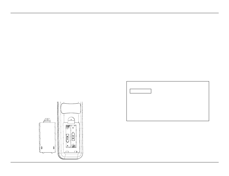
Place the supplied batteries in the remote by turning it over and removing the battery
compartment cover by slipping your fingernail under the latch and gently pulling the cover down
towards you. Place your fingernail under the tab and gently push it down and towards you to
remove the cover. Insert the two supplied AAA batteries being careful to follow the polarity
markings. Replace the cover by fitting the tabs at the bottom in first and then snapping the cover
into place. It is recommended that to hold the cover more securely, remove small Philips head
screw found in the bag with the rack mount ears and gently screw it in place. Do not over tighten.
Press the Master Power Switch on the rear panel to the left to place the SDP-25 in the Standby
mode and note that the Standby/On Indicator will light red. To turn the unit on press the Power
Toggle button on the remote or the front panel Standby/On Switch. The Power On button may
also be used. Note that the Standby/On Indicator will turn blue and the Information Display will
illuminate.
To enjoy the SDP-25 with maximum audio and video quality we recommend that you take the
time to make some initial adjustments so that the settings properly reflect your specific system
setup. Once that is done you may wish to return to some of the menus to fine tune the settings.
If your system has been installed by your dealer or a custom installer check with them as they
may have already made these adjustments and they should be left as calibrated.
MAIN MENU
The SDP-25 is a highly flexible product that allows you to customize input settings, surround
modes, and adjust other system settings. To view and navigate through the menus, press the
OSD Button on the remote and then use the Navigation buttons to move the highlight to the
setting you want to adjust. Press the Enter button to go to the setting or press the Back button
to return to the previous menu screen. To clear the menus from the screen press the OSD
Button.
The Main Menu lists the top level menu choices as shown here.
Main Menu
Input Select
Input Setup
Speaker Setup
Zone 2 Select
General Setup
Exit
NOTE: The size of the menus and other on-screen messages will change when sources have
different video resolutions. This is a normal function of the SDP-25’s video system.
Setup and Configuration / Main Menu