2 sequence output circuits, 1) photocoupler output circuit, 2) line driver output circuit – Yaskawa Sigma-5 User Manual: Design and Maintenance - Linear Motors User Manual
Page 73
3.4 Connection to Host Controller
3-27
3
Wiring and Connection
3.4.2 Sequence Output Circuits
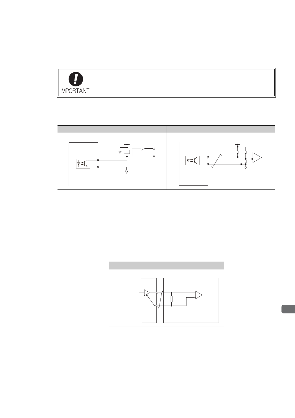
The following diagrams show examples of how output circuits can be connected the SERVOPACK.
(1) Photocoupler Output Circuit
Photocoupler output circuits are used for servo alarm (ALM), servo ready (/S-RDY), and other sequence out-
put signal circuits. Connect a photocoupler output circuit through a relay or line receiver circuit.
Note: The maximum allowable voltage and current capacities for photocoupler output circuits are as follows.
• Voltage: 30 VDC
• Current: 5 to 50 mA DC
(2) Line Driver Output Circuit
CN1 connector terminals, 17-18 (phase-A signal), 19-20 (phase-B signal), and 21-22 (phase-C signal) are
explained below.
Linear scale serial data converted to two-phase (phases A and B) pulse output signals (PAO, /PAO, PBO, /
PBO) and origin pulse signals (PCO, /PCO) are output via line-driver output circuits. Connect the line-driver
output circuit through a line receiver circuit at the host controller.
Incorrect wiring or incorrect voltage application to the output circuit may cause short-cir-
cuit.
The above failures will prevent the holding brake from working, which may damage the
machine or cause an accident resulting in death or injury.
Relay Circuit Example
Line Receiver Circuit Example
Relay
5 to 24 VDC
SERVOPACK
0 V
SERVOPACK
5 to 12 VDC
Line Receiver Circuit Example
Applicable line receiver
SN75ALS175 or the
equivalent
Host Controller
220 to
470
Ω
SERVOPACK
Applicable line driver
SN75174 manufactured
by Texas Instruments or
the equivalent