Installation and wiring, Verify drive operation, Mount the l – Yaskawa LonWorks Option Card CM048 User Manual
Page 12: Option, Installation 1-6
Installation 1-6
Installation and Wiring
The following describes the installation and configuration of the L
ON
W
ORKS
Option. For detailed information about the drive or the L
ON
W
ORKS
option, please refer to the appropriate sections of this manual or the appropriate drive user and/or technical manual..
Verify Drive Operation
Connect power to the drive and verify that the drive functions properly. This includes running the drive from the operator keypad.
Refer to the appropriate drive technical manual, for information on connecting and operating the drive.
Remove power from the drive and wait for the charge lamp to be completely extinguished. Wait at least five additional minutes for the
drive to be completely discharged. Measure the DC BUS voltage and verify that it is at a safe level.
Remove the operator keypad and terminal cover.
Mount the L
ON
W
ORKS
Option
Mount the L
ON
W
ORKS
Option onto the drive by following the instructions below. An E7 drive is shown but the procedure is identical for the P7,
F7 and G7 drives.
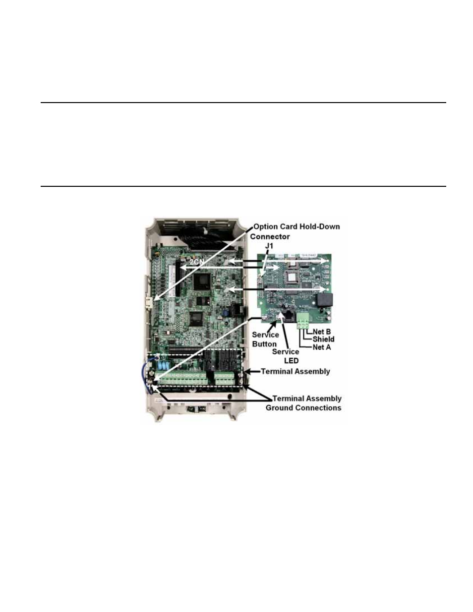
Figure 1.2 – Mount the L
ON
W
ORKS
Option
Remove the option card hold down.
Align the connector on the back of the option with its mating 2CN on the drive.
Simultaneously align the two stand-offs on the drive control board with their respective holes on the L
ON
W
ORKS
Option.
Press the option and the drive together until the connector is firmly seated and the stand-offs are locked through their associated
mounting holes.
Connect a ground wire from the Ground Terminal on the option card to a noise free control ground. If a noise free ground is not
available, leave the ground terminal on the L
ON
W
ORKS
Option un-terminated.
Connect the supplied cable (UWR00567-1) to connector J1 on the option board for the E7, P7, F7 and G7. For the E7L and E7B use
the cable appropriate for that unit (UWR00567-2 or UWR00567-3). Play close attention to keying of the J1 connector when
connecting the cable to the L
ON
W
ORKS
Option and the color coding of the wires when connecting to the drive’s terminal assembly
Route the wires down the left side of the drive’s control board and connect them to the terminal assembly as shown below.
Insert the option card hold down.