5 function description – Yaskawa AC Drive - A1000 Motion Control Custom User Manual
Page 36
5 Function Description
36
YASKAWA TM.A1000SW.117 Motion Control Custom Software Supplement
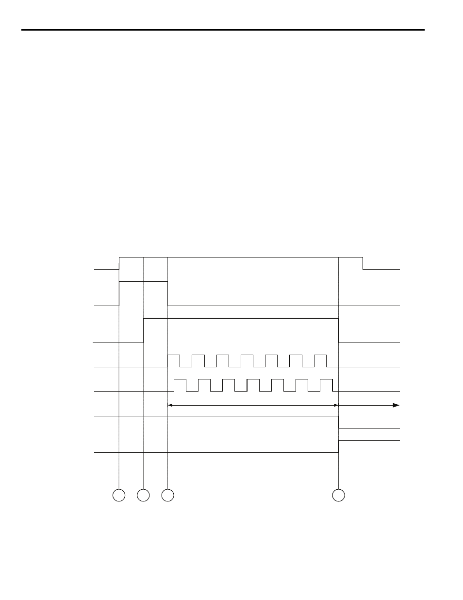
Homing When Using an Absolute Incremental Encoder
This software was designed around a TR Electronic brand encoder model #: CD65M-G/S-4096/4096-D23BB-R10NR/
N7. Please consult Yaskawa if another brand/model number of encoder is used. When P3-01 = 3 or 4 (Absolute
Incremental Encoder), and when the drive is first powered up, it reads the actual position from the serial encoder as
follows:
1. Homing begins by the drive closing its Position Request output to the encoder using the analog output on terminal FM
or AM. This will occur automatically at drive power up or when the Home Command digital input is closed.
2. The encoder responds by closing its Drive Disable output to the Drive. This signal is run into the analog input terminal
A2 or A3. The drive will not operate as long as the Drive Disable is high, as the encoder will not work in its
incremental mode. The drive will then clear its pulse counter registers. At this time, the SENCR-Serial Encoder
Reading warning will flash on the display.
3. When the drive is ready to begin counting its absolute position, it opens the Position Request output to the encoder. The
encoder will output its absolute position by sending the number pulses it is from its zero count. The drive will count the
pulses in quadrature. The drive will also monitor the direction (phase) of the A and B channels. During the sending of
the absolute position, if the encoder is rotated, the counting procedure will need to be re-run so that the encoder can
update the new position, because the encoder will send the position it is in at the beginning of the procedure. It does not
add or remove pulses during the pulsing procedure.
4. The encoder will open its Drive Disable output telling the drive to use the pulse count at that time as the absolute
position when the encoder has relayed its exact position to the drive. The drive will clear the base-block and begin
looking at the encoder for incremental feedback.
Figure 22
Figure 22 Absolute Incremental Encoder Homing Routine
0 V
10 V
12 V
0 V
Digital Input
Home Command
Analog Output (AM or FM)
Serial Enc. Pos. Req.
H4-0X = 710
Analog Input (A2 or A3)
Serial Enc. Drv. Dis.
H3-0X = 20
Encoder Channel
A + & A -
Encoder Channel
B + & B -
Digital Output
Homing Needed
Digital Output
Homing Complete
Load Absolute
PosiƟon
Incremental
Mode
1
2
3
4