Yaskawa GPD506/P5 with Apogee FLN Option User Manual
Page 14
13
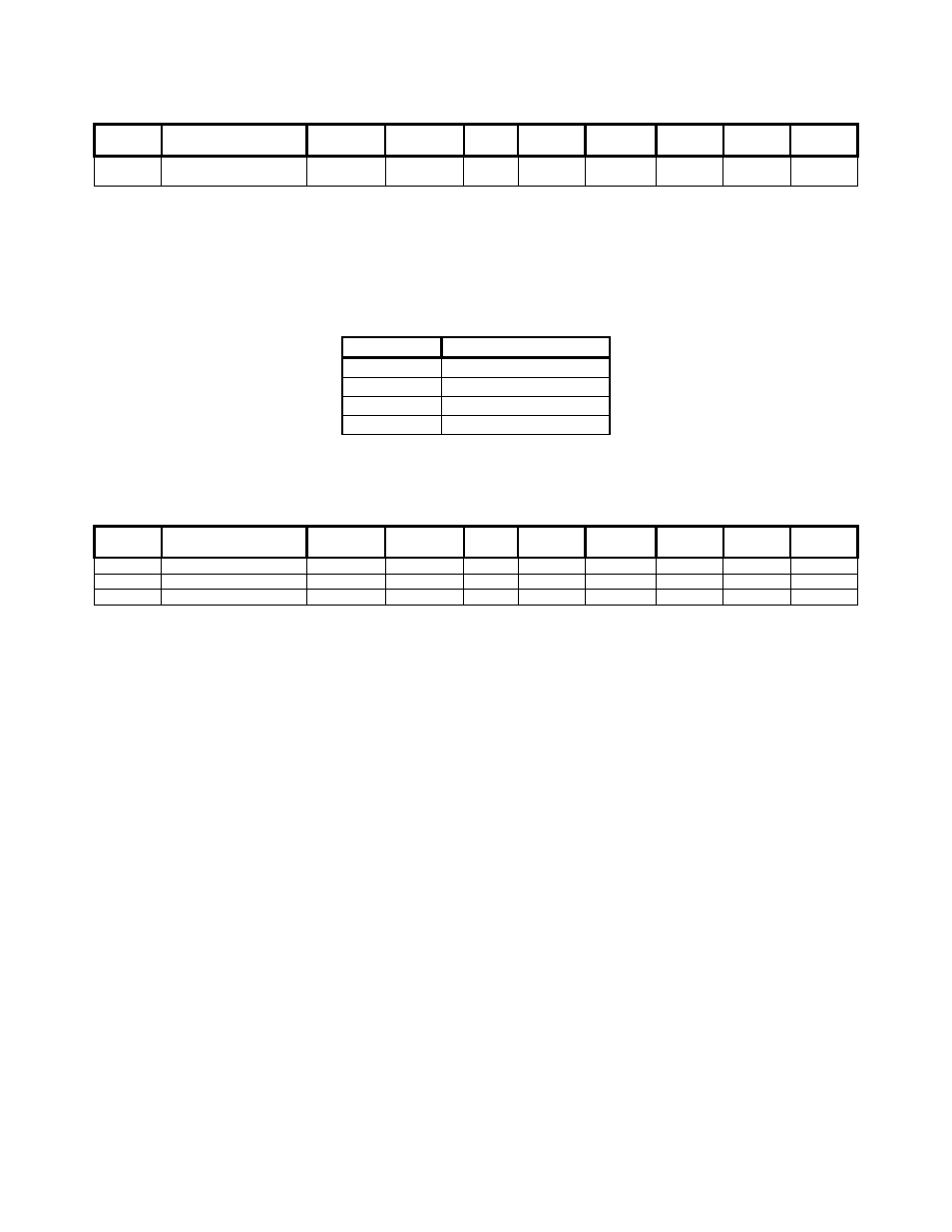
This point configures the drive as described below:
Point #
Point Description
GPD505
Parameter
GPD506/P5
Parameter
Units
(SI)
Slope Intercept Default Min
Max
55 Operational
Mode
Select
n002
n002
-
1.0 0 6 0 8
4.1.4 PID Configuration – #63, #64, #65
These points define the gains and mode of the PID controller. The PID modes selectable by #65 are
described below:
#65 PID
Mode
0 PID
Disabled
1 PID
Enabled
2
PI with Feed Forward
3 Inverted
PID
These points configure the drive as described below:
Point #
Point Description
GPD505
Parameter
GPD506/P5
Parameter
Units
(SI)
Slope Intercept Default Min
Max
63
PID Proportional Gain
n086
n086
-
0.1
0
1.0
0.0
10.0
64
PID Integral Time
n087
n087
Sec
0.1
0
10.0
0.0
100.0
65
PID Mode Select
n084
n084
-
1.0
0
0
0
3
4.1.5 General Purpose Setup – #72, #73
Two points are defined for setting any drive parameter:
#72 - Specifies the drive parameter to be set. Writing to this point initiates the write sequence.
#73 - Specifies the value to be written to the specified parameter. Writing to this point completes the
write sequence and causes the value to be sent to the drive.
Refer to the appropriate Technical Manual for a detailed description of all parameters.
NOTE: The increment listed in the Technical Manual must be considered when specifying a value.
For example, to set GPD506/P5 parameter n070 (GPD505 n066), DC Injection Time at Stop,
to 1 second, #73 must be set to 10, since the increment for this parameter is 0.1 seconds.