Yaskawa VCD 723 User Manual
Page 16
1
Introduction
10
Ratings and Specifications
9/15/93
28,29
30
31
32
51
52
53
54
55,56
57
58
59,60,61,62
63
64
65,66,67,68
69
70
71,72,73,74
Connector
CA1
Logic outputs,
open collector
Motor
thermistor input
Motor
thermistor input
common
Shield tie point
+10VREF
output
-10VREF
output
I/O common
Shield tie point
Analog outputs
I/O common
Shield tie point
Analog input
I/O common
Shield tie point
Analog input
I/O common
Shield tie point
Digital
Tachometer
inputs
Digital
Tachometer
Connector
Photocoupler isolated output. Capacity of +48 VDC
max at 50 mA max.
Motor temperature feedback.
Common (0V) for use in wiring motor thermistor input.
Shield sheath tie point which is connected to Chassis
Common.
Reference voltage output for use with MicroTrac card
analog inputs. 10 mA max capacity.
Reference voltage output for use with MicroTrac card
analog inputs. 10 mA max capacity.
Common (0V) for use with MicroTrac card I/O.
Shield sheath tie point which is connected to Chassis
Common.
Non-isolated -10 to +10 VDC analog outputs.
Maximum sourcing current is 2 mA. Resolution is
12 bits.
Common (0V) for use with MicroTrac card I/O.
Shield sheath tie point which is connected to Chassis
Common.
Non-isolated differential analog input. Input has over
100K ohms of impedance. Resolution is 12 bits. Input
voltage range is -600 to +600 mV when terminals 60 (+)
and 61 (-) are used. Input voltage range is -10 to +10
VDC when terminals 59 (+) and 62 (-) are used.
Common (0V) for use with MicroTrac card I/O.
Shield sheath tie point which is connected to Chassis
Common.
Non-isolated differential analog input. Input has over
100K ohms of impedance. Resolution is 12 bits. Input
voltage range is -600 to +600 mV when terminals 66 (+)
and 67 (-) are used. Input voltage range is -10 to +10
VDC when terminals 65 (+) and 68 (-) are used.
Common (0V) for use with MicroTrac card I/O.
Shield sheath tie point which is connected to Chassis
Common.
The quadrature encoder A (terminal 71), /A (terminal
72), B (terminal 73), and /B (terminal 74) signals are
connected here. There is 100 ohms of impedance
between each pair of encoder input signals. Input
differential voltage of 5 VDC max. The maximum
input frequency is 300KHz.
Isolated +12 VDC power supply to quadrature encoder
and quadrature encoder signal inputs.
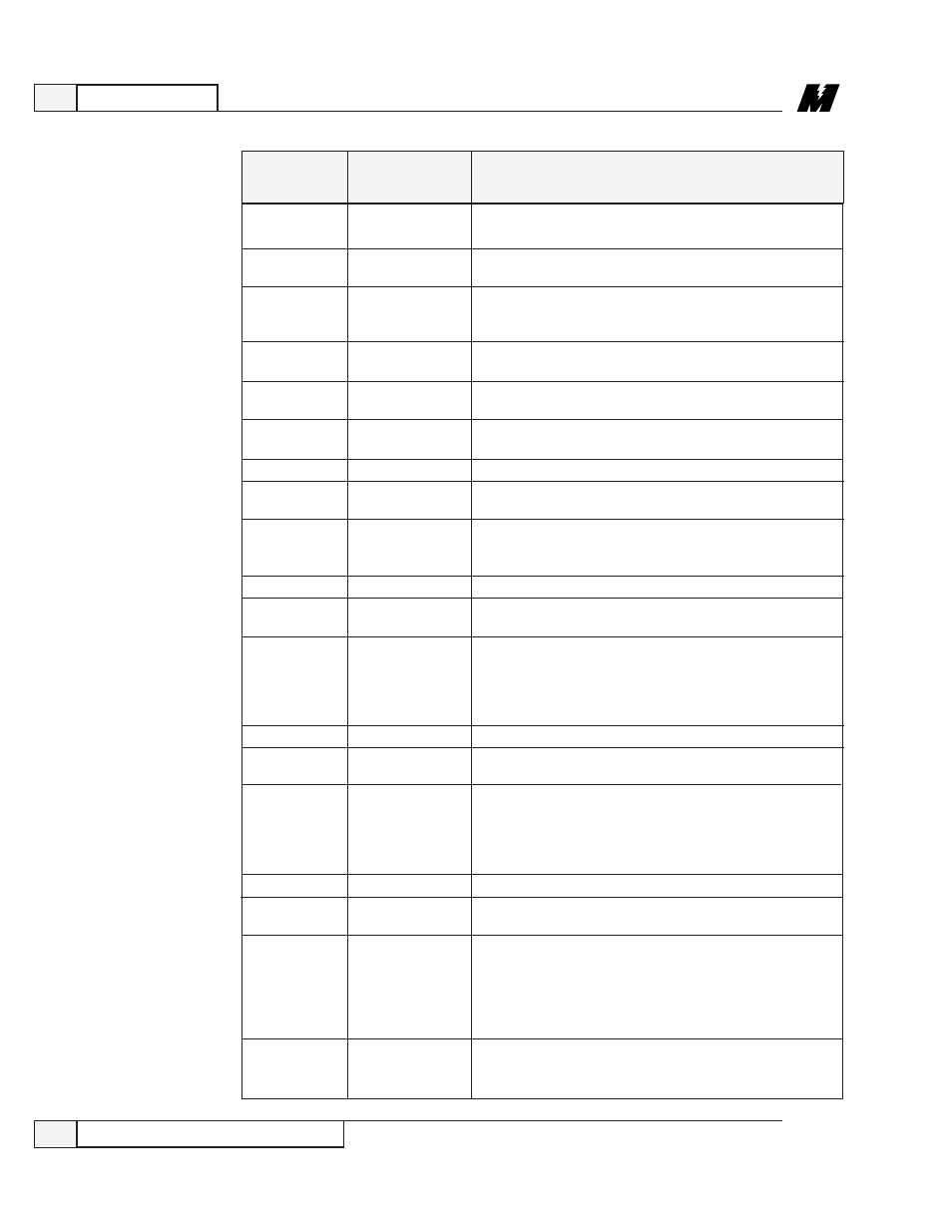
Table 2. Terminal I/O Specifications - Continued
TERMINAL
FUNCTION
DESCRIPTION