Yaskawa VS-616G5 DeviceNet Communication Interface Card SI-M2 User Manual
Page 4
Page 4
VS-616G5 Option Instruction Manual: DeviceNet™ Communication Interface Card SI-M2
INSTALLATION
1. Before attempting to install or use the DeviceNet
Communication Interface Card SI-M2, read these
instructions.
2. After unpacking the card, verify that the code number is correct and that no damage occurred during
shipping. Contact your YASKAWA representative if you should require any assistance.
3. Turn OFF the main electrical power to the inverter.
4. Remove the inverter’s cover by first removing the digital operator. Then push inward (on the cover)
at the indented area located on each side of the cover, and lift the cover upward pivoting from the rear
of the cover. (Refer to the VS-616G5 User’s Manual, if necessary).
5. Check that the indicator CHARGE lamp is OFF (power OFF indication).
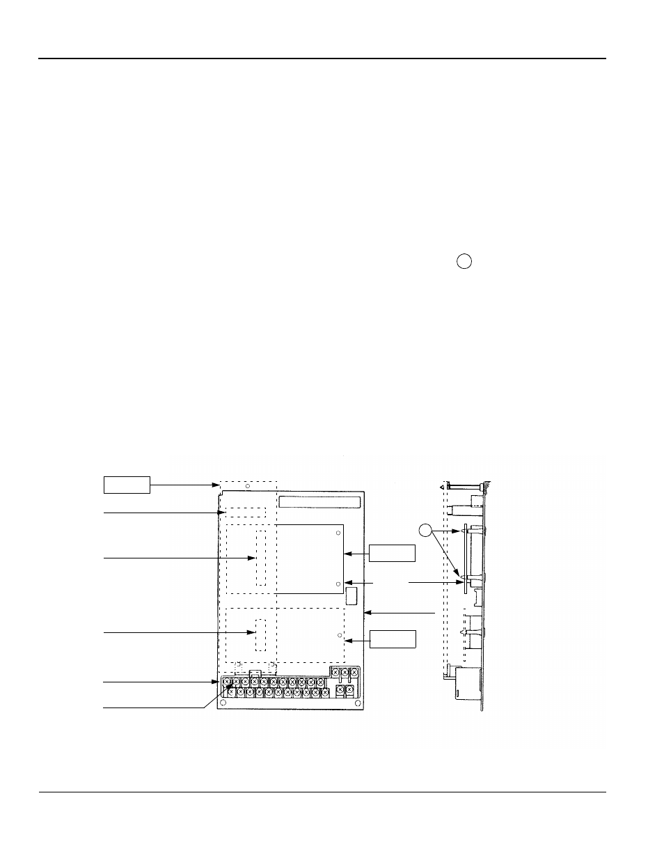
6. Plug the 2CN connector of DeviceNet
Communication Interface Card SI-M2 into the 2CN connec-
tor (60 pins) on the control board of the inverter. Gently push the SI-M2 card until the stand-off posts
engage the two holes on the option card. Secure the SI-M2 card. (See part A of the side view).
7. Attach the green ground wire to terminal 12 of the VS-616G5 control board.
8. Connect an appropriate Flash ROM writing cable to the 1CN connector on the inverter’s control
board. If so equipped, set the cable’s switch to Flash writing mode.
9. Apply power to the VS-616G5 unit.
10. Write the VS-616G5’s Flash ROM using the required DeviceNet
Flash software.
11. Set the VS-616G5’s MAC ID, Baud Rate, Output Assy Inst, and Input Assy Inst. These settings are in
the “Group P DeviceNet
menus”.
12. Cycle the power to the VS-616G5. This must be done so that the inverter will recognize the new
MAC ID and Baud Rate settings. In a multiple unit installation, this can be done after the last unit is
setup.
13. Replace the inverter’s cover. Refer to Fig. 3 for correct wiring of the DeviceNet
Communication
Interface Card SI-M2 and the control board.
14. The hardware and software installation is now complete.
Option A
7CN
Top
Option C
Option D
Control board
Bottom
Front View
Grounding terminal 12
Connector
3CN Option D connector
2CN Option C connector
4CN Option A connector
terminal
Mounting base
A
Side View
Fig. 2 Installation of the DeviceNet
Communication Interface Card SI-M2
SI-M2
of inverter