Gpd515/g7 to f7 terminal comparison – Yaskawa GPD 515/G5 to F7 User Manual
Page 13
Product Transition Guide
GPD515/G5 to F7
__________________________
PL.F7.02.TransitionGuide 6/5/06
Page 13 of 40
Yaskawa Electric America, Inc
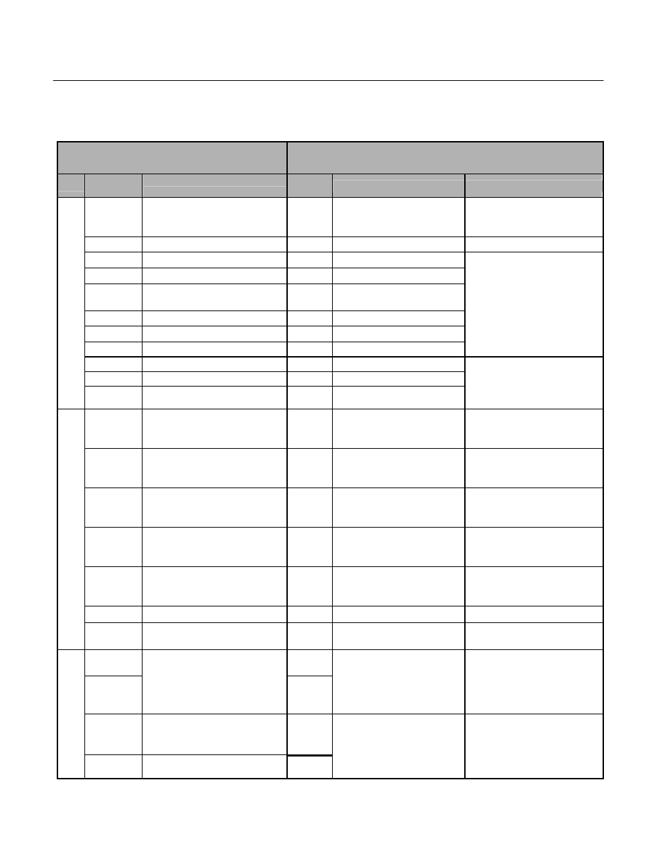
GPD515/G7 to F7 Terminal Comparison
The factory default functions 2-wire control are shown
GPD515/G5 Terminal
F7 Terminal
(Designations similar to GPD506/P5)
Type
GPD515/G5
Terminal
Default Function
F7
Terminal
Default Function
F7 Description
1
Forward run/stop
Signal level: (Photo-coupler
insulated Input: +24VDC, 8mA)
S1
Forward run/stop command
–
2
Reverse run/stop
S2
Reverse run/stop command
–
3
External fault input
S3
External fault input
4
Fault reset input
S4
Fault reset
5
Master/Aux. change
Multi-step speed ref.1
S5
Multi-step speed reference 1
(Master/auxiliary switch)
6
Multi-step speed ref.2
S6
Multi-step speed reference 2
7
Jog reference
S7
Jog frequency reference
8
External baseblock
S8
External baseblock N.O.
Multi-function digital inputs.
Functions set by:
H1-01 to H1-06.
24 VDC, 8 mA
Photo coupler isolation
11
Sequence control input common
SN
Digital input common
–
SC
Factory connected to SP
Dig
ital In
pu
t Sig
n
als
–
SP
Factory connected to SC
Factory connected for internal
supply sinking mode.
Refer to F7 User Manual for
other methods.
15
+15V Power supply output for
analog command
(Allowable current 20 mA max.)
+V
+15Vdc power output
+15Vdc (Max. current: 20 mA)
33
-15V Power supply output for
analog command
(Allowable current 20mA max.)
-V
-15Vdc power output
-15Vdc (Max. current: 20 mA)
13
Master frequency ref. (voltage)
-10 to +10V (20k ohms)
0 to +10V/(20k ohms)
A1
Analog input or speed
command
0 to +10Vdc=100%
0 to +/-10Vdc =100% (H3-01)
(20k ohm)
14
Master frequency ref. (current)
4 to 20mA (250 Ohms)
A2
Add to terminal A1
4 to 20 mA=100%/(250 ohms)
0 to +10Vdc=100%/(20kohm)
Function set by H3-09.
16
Multi-function analog input
-10 to +10V (20k ohms),
0 to +10V/(20k ohms)
A3
Aux. frequency reference 1
0 to +10Vdc=100%/(20 kohm)
0 to +/-10Vdc=100%
Function set by H3-05
17
Common for control circuit 0V
AC
Analog common
–
Anal
og
I
n
put
S
ignal
s
12
Connection to shield sheath of
signal lead
E(G)
Shield wire, optional ground
line connection point
–
9
M1
10
During running (NO contact)
Dry contact capacity: 250VAC,
1A or less 30VDC, 1A or less
M2
During run
(N.O. contact)
Form A Dry contacts capacity:
1 A max. at 250Vac
1 A max. at 30Vdc
Multi-function digital output.
Function set by H2-01.
25
Zero speed detection
Open collector output
48V, 50mA or less
M3
Dig
ital Ou
tpu
t
Sig
n
als
27
Open collector output common
M4
Zero speed
(N.O. contact)
Form A Dry contacts capacity:
1 A max. at 250Vac
1 A max. at 30Vdc
Multi-function digital output.
Function set by H2-02.