Monitor codes, 10 cc-link code numbers – Yaskawa 1000 Series Drive Option - CC-Link Technical Manual User Manual
Page 28
10 CC-Link Code Numbers
28
YASKAWA ELECTRIC SIEP C730600 44A YASKAWA AC Drive-Option Card CC-Link Technical Manual
◆
Monitor Codes
Table 20 Monitor Codes
11FH
–
Number of pulse 2 speed detection
120H
–
Fault contents 1
121H
–
Fault contents 2
122H
–
Fault contents 3
123H
–
Fault contents 4
124H
–
Fault contents 5
130H
–
CPF contents 1
131H
–
CPF contents 2
132H
–
CPF contents 3
<1> See
Fault and Minor Fault Contents on page 29
for information on fault contents.
Monitor Code
Name
Comments
0000H
Reserved
0001H
Output frequency
Units are determined by o1-03.
0002H
Output current
Units are either 0.1 A or 0.01 A, depending on the capacity of the drive.
0003H
Output voltage reference
Units: 0.1 V
0004H
Reserved
0005H
Frequency reference
Units are determined by o1-03.
0006H
Motor speed
Units: 1 r/min
0007H
Motor torque
Units: 0.1%
0008H
DC bus voltage
Units: 1 V
0009H
Reserved
000AH
Reserved
000BH
Reserved
000CH
Reserved
000DH
Reserved
000EH
Output power
Units: 0.1 kW
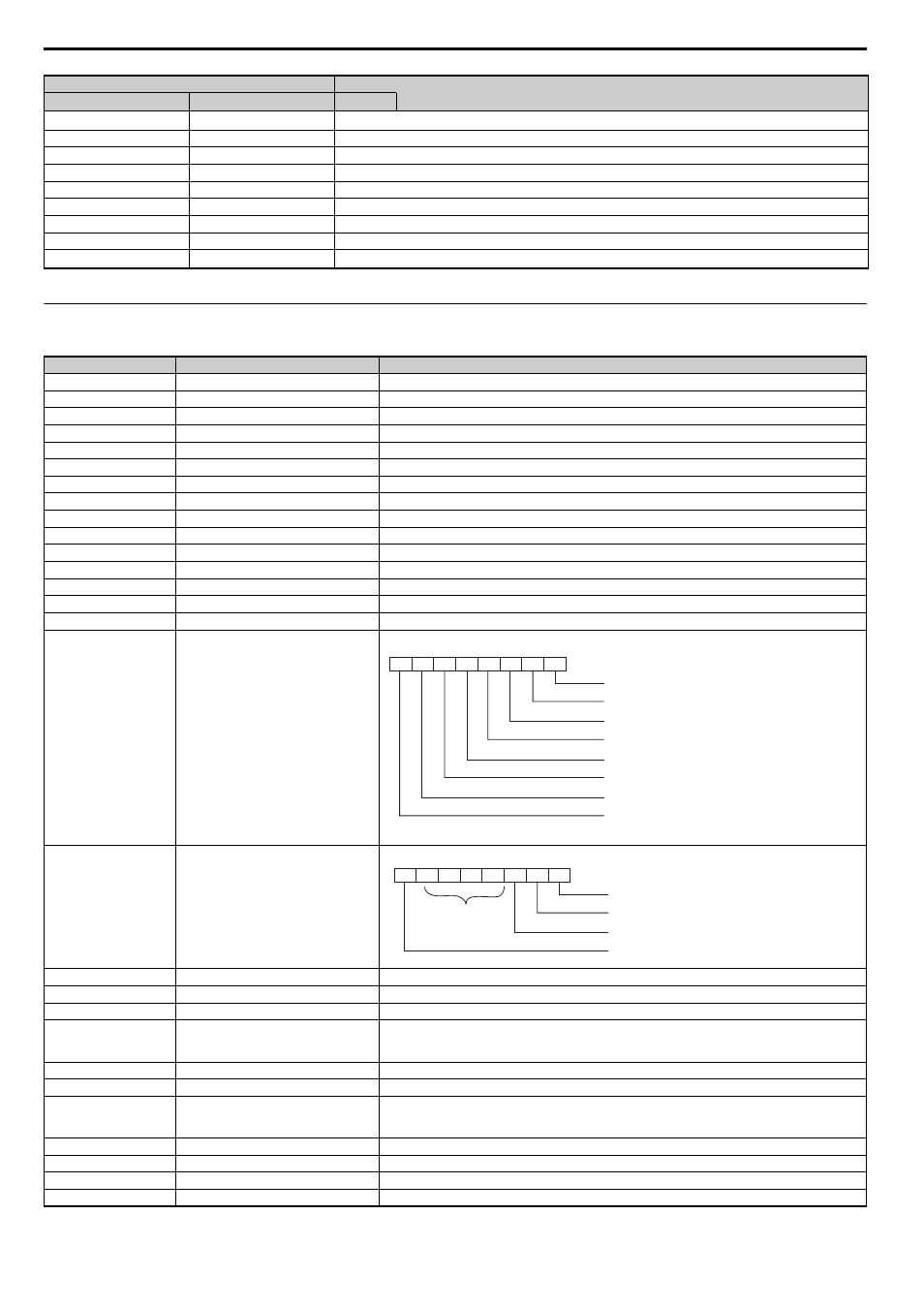
000FH
Input terminal status
0010H
Output terminal status
0011H
Reserved
0012H
Motor excitation current
Units: 0.1%
0013H
Reserved
0014H
Cumulative operation time
• Units: 1 hour
• Parameter o4-02 determines if the operation time is the considered to be whenever the drive powered on or
only when there is voltage output.
0015H
Reserved
0016H
Reserved
0017H
Actual operation time
• Units: 1 hour
• Parameter o4-02 determines if the operation time is the considered to be whenever the drive powered on or
only when there is voltage output.
0018H
Motor secondary current
0019H
Cumulative power
Units: 4 kW
0034H
PID setpoint
Units: 0.1%
0035H
PID input
Units: 0.1%
Command Code
Name
Read
Write
BIT
7
6
5
4
3
2
1
0
Multi-Function Digital Input 1 (terminal S1 enabled)
Multi-Function Digital Input 2 (terminal S2 enabled)
Multi-Function Digital Input 3 (terminal S3 enabled)
Multi-Function Digital Input 4 (terminal S4 enabled)
Multi-Function Digital Input 5 (terminal S5 enabled)
Multi-Function Digital Input 6 (terminal S6 enabled)
Multi-Function Digital Input 7 (terminal S7 enabled)
Multi-Function Digital Input 8 (terminal S8 enabled)
1: ON
RW
0: OFF
7
6
5
4
3
2
1
0
Multi-Function Digital Output (terminal M1-M2) enabled
Multi-Function Digital Output 1 (terminal P1) enabled
Multi-Function Digital Output 2 (terminal P2) enabled
Fault Contact Output (terminal MA/MB-MC) enabled
1: ON
RW
0: OFF
Not used