Communication cable wiring, 5 installation procedure – Yaskawa 1000 Series Drive Option - CC-Link Technical Manual User Manual
Page 14
5 Installation Procedure
14
YASKAWA ELECTRIC SIEP C730600 44A YASKAWA AC Drive-Option Card CC-Link Technical Manual
◆
Communication Cable Wiring
■
Procedure
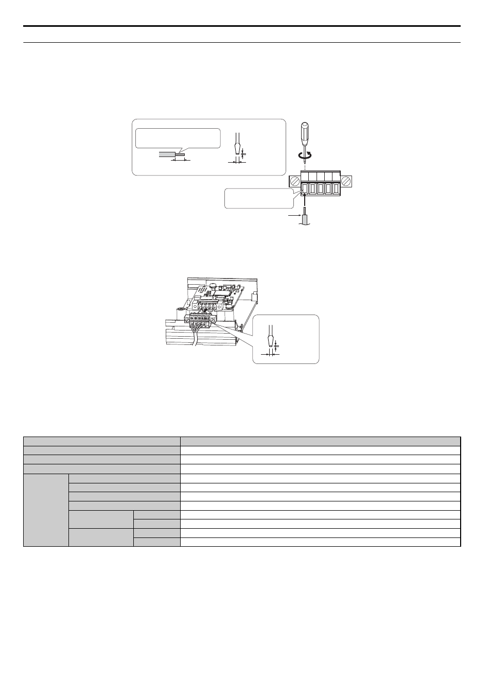
Follow the instructions below to connect the communications cable to the terminal block.
NOTICE: Tighten all terminal screws according to the specified tightening torque. Failure to comply can cause a short-circuit or drive malfunction.
1.
Connect the communications cable to the terminal block as shown in the diagram below.
Note: Communication lines should be separated from main circuit wiring and other electrical lines. (Tightening torque: 0.22 to 0.25 (Nxm))
Figure 6
Figure 6 Comm Cable Wiring
2.
Take particular precautions to ensure that each cable is properly connected, and that wire covering has not been accidentally inserted into
the terminals.
3.
After the terminal block is fully attached to the CC-Link option, tighten the screws on the left and right sides of the terminal block. (Tightening
torque: 0.22 to 0.25 (Nxm))
Figure 7
Figure 7 Terminal Block Installation
■
Communication Cable Specifications
Use only CC-Link dedicated communication cable; the Yaskawa warranty does not cover other cable types. For more information on cables, refer to
the CC-Link website at http://www.cc-link.org/.
Yaskawa recommends using CC-Link cables suitable for the conditions listed in
.
Table 5 Communication Cable Requirements
Item
Specifications
Cable Type
triple-core shielded twisted-pair cable
Gauge
8.0 mm max
Drain Wire
20 lines / 0.18 mm or 24 lines / 0.18 mm
Electrical
Characteristics
Conductor Resistance (20
°C)
37.8
Ω/km
Insulation Resistance
10000 M
Ωkm or more
Voltage Tolerance
500 Vdc, 60 s
Capacitance (1 kHz)
60 nF/km max
Impedance
1 MHz
110 ±15
Ω
5 MHz
110 ± 6
Ω
Attenuation (20
°C)
1 MHz
1.6 dB / 100 m max
5 MHz
3.5 dB / 100 m max
DA DB DG SLD SLD
Terminal block
Preparing wire ends:
Screwdriver blade size
When not using
terminal extensions
about 5.5 mm
Pull back the sheilding and lightly
twist the end with fingers, keeping
the ends from fraying
CC-Link comm cable
(do not soldered ends)
Loosen the screws and
insert the cable into the
opening on the terminal block
Blade depth of
0.4 mm or less
Blade width of
2.5 mm or less
screwdriver blade size
Blade depth of
0.6 mm or less
Blade width of
3.5 mm or less