5 installation procedure – Yaskawa 1000 Series Drive Option - CC-Link Technical Manual User Manual
Page 15
5 Installation Procedure
YASKAWA ELECTRIC
SIEP C730600 44A YASKAWA AC Drive-Option Card CC-Link Technical Manual
15
Figure 8
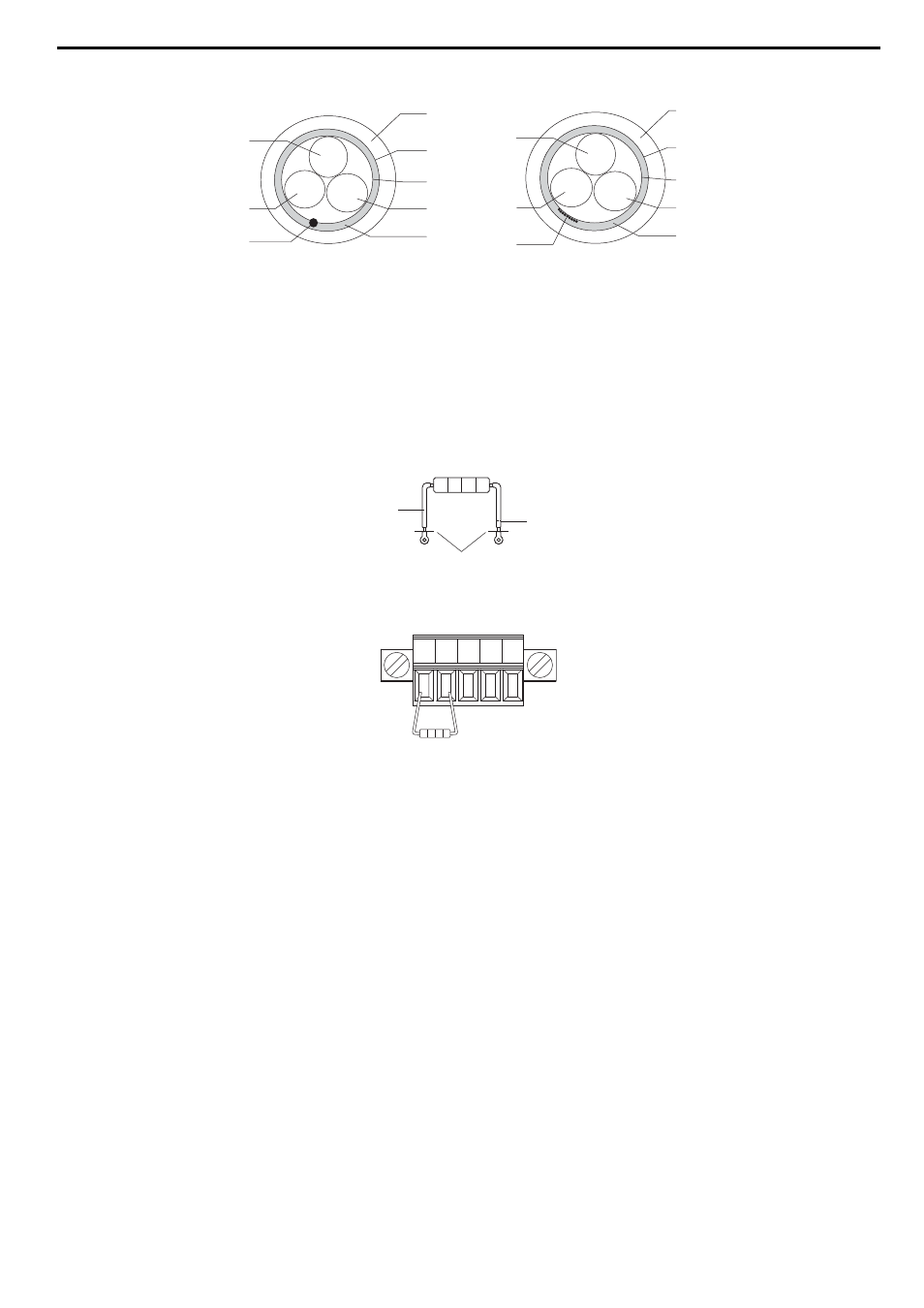
Figure 8 Cable Diagram
■
Terminal Resistor Connection
When the CC-Link Option is the last station connected in a CC-Link network, the terminal resistor needs to be set to that CC-Link Option. Follow
the instructions below.
1.
Cut the terminal resistor tube as shown.
Note: For the terminal resistor, either use what is already built into the master unit, or use a standard-market resistor of 110
Ω, ±5% (1/2 W).
Figure 9
Figure 9 Terminal Resistor
2.
Loosen the attachment screw and insert the terminal resistor described in the first step between terminals DA and DB.
Figure 10
Figure 10 Terminal Resistor Wiring
A – sheath
F – drain (concentrated)
B – shield
G – DB
C – aluminum tape
H – DA
D – DG
I – drain (spread out)
E – ground
A
B
C
D
E
H
G
F
white
blue
yellow
A
B
C
D
E
H
G
I
white
blue
yellow
jumper
cut here
cut
DA DB DG SLD SLD
- Tag Generator (30 pages)
- MP3300iec (82 pages)
- 1000 Hz High Frequency (18 pages)
- 1000 Series (7 pages)
- PS-A10LB (39 pages)
- iQpump Micro User Manual (300 pages)
- 1000 Series Drive Option - Digital Input (30 pages)
- 1000 Series Drive Option - CANopen (39 pages)
- 1000 Series Drive Option - Analog Monitor (27 pages)
- 1000 Series Drive Option - CANopen Technical Manual (37 pages)
- 1000 Series Drive Option - CC-Link (38 pages)
- 1000 Series Drive Option - DeviceNet (37 pages)
- 1000 Series Drive Option - DeviceNet Technical Manual (81 pages)
- 1000 Series Drive Option - MECHATROLINK-II (32 pages)
- 1000 Series Drive Option - Digital Output (31 pages)
- 1000 Series Drive Option - MECHATROLINK-II Technical Manual (41 pages)
- 1000 Series Drive Option - Profibus-DP (35 pages)
- AC Drive 1000-Series Option PG-RT3 Motor (36 pages)
- Z1000U HVAC MATRIX Drive Quick Start (378 pages)
- 1000 Series Operator Mounting Kit NEMA Type 4X (20 pages)
- 1000 Series Drive Option - Profibus-DP Technical Manual (44 pages)
- CopyUnitManager (38 pages)
- 1000 Series Option - JVOP-182 Remote LED (58 pages)
- 1000 Series Option - PG-X3 Line Driver (31 pages)
- SI-EN3 Technical Manual (68 pages)
- JVOP-181 (22 pages)
- JVOP-181 USB Copy Unit (2 pages)
- SI-EN3 (54 pages)
- SI-ET3 (49 pages)
- MECHATROLINK-III (35 pages)
- EtherNet/IP (50 pages)
- SI-EM3 (51 pages)
- 1000-Series Option PG-E3 Motor Encoder Feedback (33 pages)
- 1000-Series Option SI-EP3 PROFINET (56 pages)
- PROFINET (62 pages)
- AC Drive 1000-Series Option PG-RT3 Motor (45 pages)
- SI-EP3 PROFINET Technical Manual (53 pages)
- A1000 Drive Option - BACnet MS/TP (48 pages)
- 120 Series I/O Modules (308 pages)
- A1000 12-Pulse (92 pages)
- A1000 Drive Software Technical Manual (16 pages)
- A1000 Quick Start (2 pages)
- JUNMA Series AC SERVOMOTOR (1 page)
- A1000 Option DI-101 120 Vac Digital Input Option (24 pages)