9 communication, Communication – SMA AUTOMATIC SWITCH BOX M User Manual
Page 33
SMA Solar Technology AG
Electrical Connection
Installation Guide
AS-BoxM-IEN091711
33
5.9 Communication
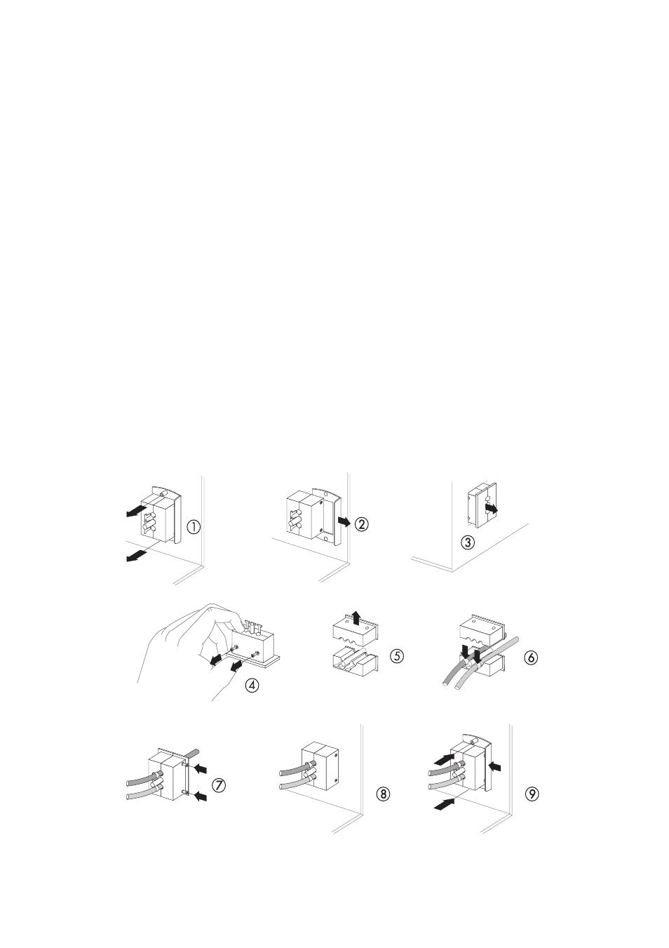
Preparatory Work:
1. Loosen the screws of the fastening plate of the dual cable gland inside the Automatic Switch
Box.
2. Remove fastening plate and place to the side.
3. Remove cable gland from the housing.
4. Loosen screws of the dual cable gland.
5. Detach the half without the T-shaped fastening pieces.
6. Lay the communication cable as well as the control and measurement cable with sufficient
length from the gland to the desired connection through the part of the cable gland with the
T-shaped fastening pieces and fix them with cable ties.
7. Screw both halves back together. Fasten the screws so that they could be loosened by hand.
The cables as well as the placeholder (plastic rod) have to be fitted tightly between both sides
of the dual cable gland. Otherwise, a proper seal of the housing cannot be guaranteed.
8. Insert cable gland including cable into the housing.
9. Attach fastening plate of the dual cable gland and fasten screws by hand.
☑ The cables are led into the Automatic Switch Box.