2 connecting loads, Connecting loads – SMA AUTOMATIC SWITCH BOX M User Manual
Page 16
Electrical Connection
SMA Solar Technology AG
16
AS-BoxM-IEN091711
Installation Guide
5.2 Connecting Loads
The cables of the loads are led through fuse elements in the Automatic Switch Box. The fuses are
necessary in order to protect the output cable from overload in stand-alone grid operation. Note that
in stand-alone operation, both the Sunny Backup as well as the PV system can power the loads, and
the upstream fuse on the grid side has no effect in this situation. Determine the required fuse size
according to layout type of the cable and installation conditions, and install appropriate fuse plugs.
The maximum fuse plugs D02 with a nominal current of 35 A which may be used are included in the
scope of delivery.
Cable Requirements
The cable type and laying method must be suitable for the application and use location.
DANGER!
Risk of death from feedback of the Sunny Backup system into the public grid.
In case of backup, feedback into the public grid can occur through the backup phase and
the 3-phase loads.
Feeding of the PV system and potentially from the diesel generator only occurs at phase L1
in case of grid failure.
• When connecting 3-phase loads whose coils or resistors are switched in a triangle,
always connect all three phases to the Automatic Switch Box.
Selectivity of thermal fuses
In unfavorable constellations (e.g. the same fuse value twice in a row), it may happen that
it is not possible to select whether to install the thermal fuses as upstream or downstream
fuses. This is unavoidable due to the complexity of the Sunny Backup system with several
feeding sources.
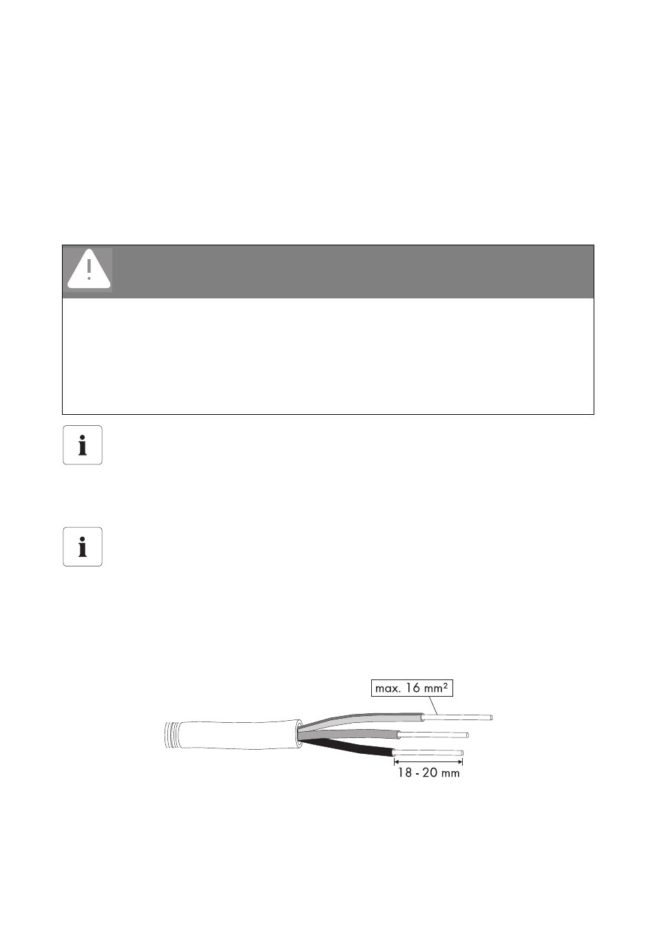
Cable end sleeves
When using fine-wired cables, use cable end sleeves as well.
This only applies to cables connected to the "F5 Backup Loads" fuse element.
Cable cross section