SMA 600-US User Manual
Page 39
SMA America, LLC
6 Electrical Connection
Installation Manual
CU600-1000US-IA-en-10
39
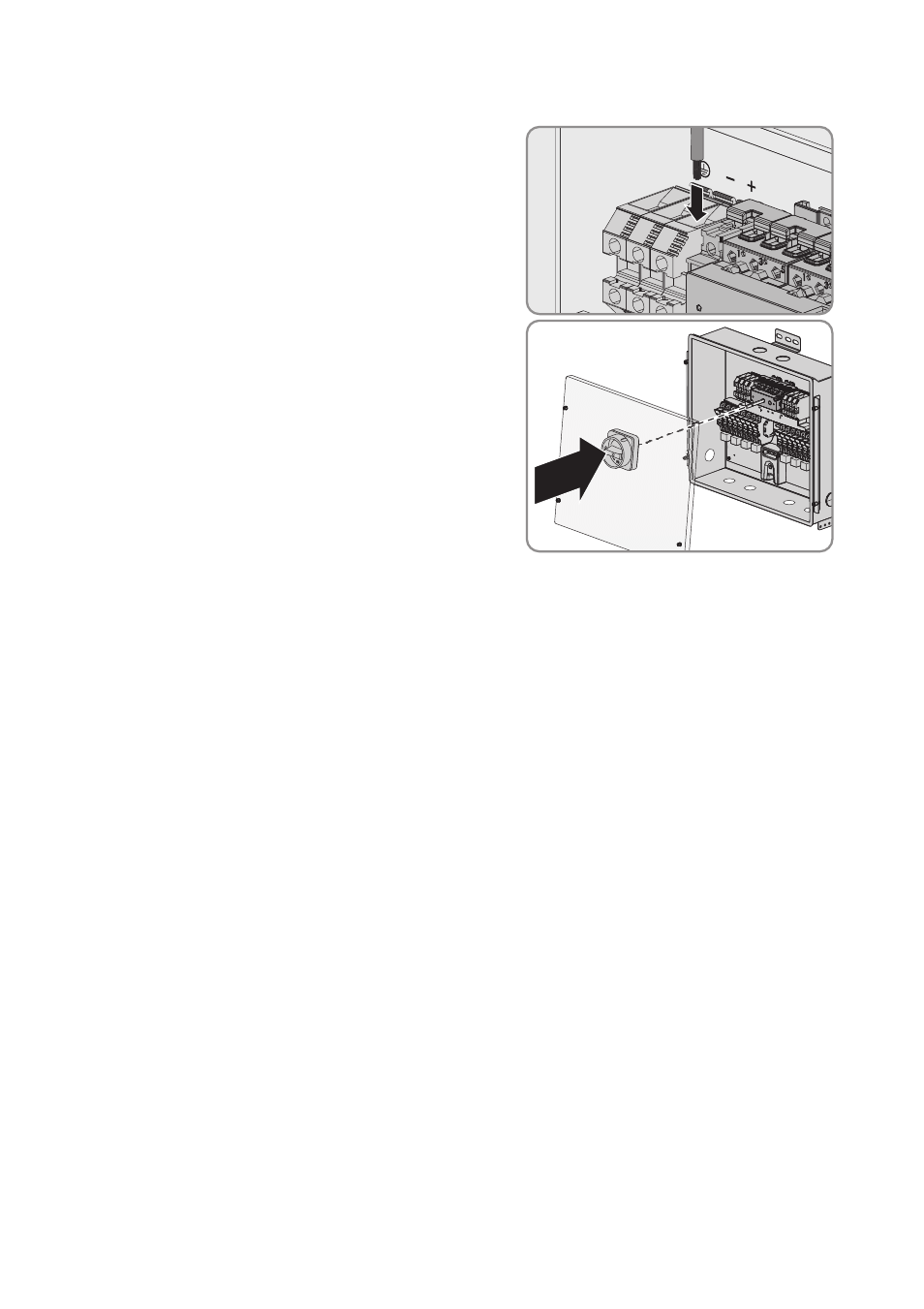
5. Connect a cable to the screw terminal with the plus
sign for connecting the Connection Unit to the
inverter
6. Tighten the screw terminals with a screwdriver
(blade width: 6 mm) (torque 51 in-lb. (5.8 Nm)).
7. Mount the lid of the Connection Unit:
• Position the lid in such a way that the protruding
shaft in the Connection Unit snaps into the
provided opening of the DC
switch-disconnector.
• Tighten all lid screws with an Allen key (AF 4)
(torque: 35 in-lb. (4 Nm)).
8. In order to protect the DC switch-disconnector
against restarting, lead the shackle of the padlock through the opening in the switch and lock it.
9. Lead the connected DC output cables through the conduit of the Connection Unit and connect
to the inverter (see inverter installation manual).