Connection unit – SMA 600-US User Manual
Page 38
6 Electrical Connection
SMA America, LLC
38
CU600-1000US-IA-en-10
Installation Manual
6.8 Connecting the DC Output Cable for the Inverter to the
Connection Unit
Additionally required mounting material (not included in the scope of delivery):
☐ Two cables for connecting the Connection Unit to the inverter.
☐ If the DC switch-disconnector should be protected against restarting, a padlock can be used.
Cable requirements:
☐ The DC output cables must be designed in accordance with the installation requirements
applicable on site and for temperatures of +194°F (+90°C).
☐ Cable type: copper wire
☐ Use only solid wire or rough wire strands.
☐ Conductor cross-section: AWG 8 to AWG 2 (10 mm² to 35 mm²)
Padlock requirements:
☐ The material must be non-corrosive and weather-proof.
☐ The shackle of the padlock must be hardened.
☐ The lock cylinder must be secured.
Requirements:
☐ The conduits must be correctly connected to the Connection Unit (see Section 6.3).
☐ The DC switch-disconnector must be switched OFF and the lid must be dismantled.
Procedure:
Connect the DC output cables for connecting the Connection Unit to the inverter for INPUT A and
INPUT B as follows:
2. Strip the insulation of the cable ends of the two cables for connecting the Connection Unit to the
inverter by
5
⁄
16
in. (18 mm).
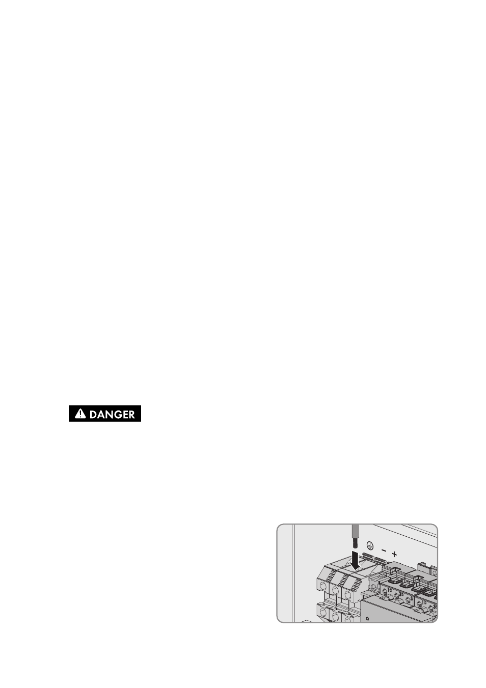
3. Connect a cable to the screw terminal with the
minus sign for connecting the Connection Unit to the
inverter.
4. Tighten the screw terminals with a screwdriver
(blade width: 6 mm) (torque 51 in-lb. (5.8 Nm)).
1.
Danger to life due to electric shock
• Make sure all devices connected to the Connection Unit (e.g inverter) are switched off
and protected against reconnection (see manual of the respective device).
• Cover the PV modules.