Diagram f – ShoreLand'r SLKB150TA User Manual
Page 10
Midwest Industries, Inc.
Ida Grove, IA 51445
800.859.3028
www.shorelandr.com
0003957
Page 10
04/10/2008
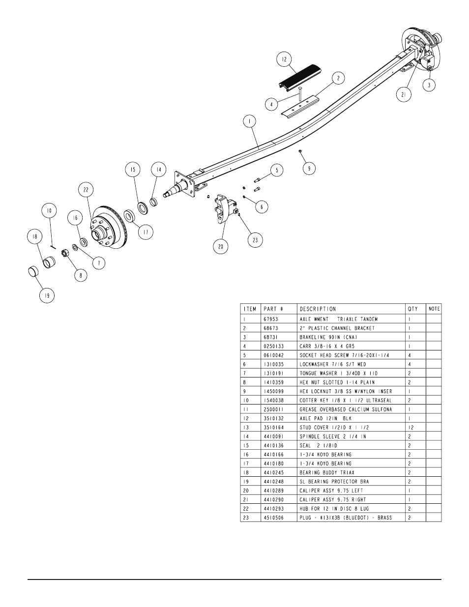
Diagram F
spring bushing just placed above the hook spring leaf. Secure us-
ing a 9/16” lock nut. Repeat on the other spring.
Brake Line Installation
Sort all of the items in hardware box No. 68141. Locate the long
(90’) brake lines and straighten out by uncoiling on a concrete
floor while walking on the line as you uncoil. The line should be
made as straight as possible to assist in mounting to the axle.
Locate five (5) line clamps and 1/4” self tapping screws provided
in the kit. Hold the line on the backside of the axle and familiarize
yourself on how it needs to be formed to connect to the brass
blocks on the brake calipers. Form the line so that it can be
routed down the back side of the axle and then over to the brass
block on the calipers.
Remove the lower brass plug from the port in the brass block on
the left brake caliper. Note also that the bolt holding the brass
block to the caliper can be loosened so that the brass block can
be rotated to better accommodate the angle that the brake line
approaches the block on the caliper. Thread the brake line
fitting into this port to hold the line in position making sure
that the line does not rub or touch the spring. Re-tighten the
bolt in the brass block if it has been loosened to rotate the block.
Route the line along the back side of the axle and secure to
the axle with the five (5) clamps and self tapping screws.
Note that the axle is pre-drilled for the mounting screws.
Route the brake line over to the brass block on the right brake
caliper. Remove both plugs on the right caliper block. Thread the
other end of the brake line into the bottom port on the brass block.
Thread the 13” brake hose male end into the other port. Tighten.
Position the brass block so that neither the hose nor the brake line
will contact or rub the spring.
Tighten all fittings.
Place the other end of the hose up through the hole provided in
the brake line clip bracket. Secure in place with the hose clip pro-
vided.
Repeat this process on the second and third axles.
Connecting the Three Axles Together
Locate the two brass tees. Thread the male port of the tees into the
female end of the 13” brake hoses running up from the axles just
installed on the front and second axles. Tighten.
Remove the plastic cap from the end of the frame brake line com-
ing out of the side frame by the axle. Carefully uncoil the brake line
enough so that it will reach the port of the tee just threaded into the
brake hose. Thread the brake line fitting into the top port of the tee
installed on the front axle and tighten.