ShoreLand'r SLR95TAL User Manual
Page 4
Springs:
Position the axles so they are
properly aligned with the trailer. The
disc brake calipers are on the back
side of the axle.. Drop two 1/2” x 2-
9/16” x 6-1/2” stainless steel U-
bolts down over the axle, then
down through the holes in the
spring mounting plate that is
welded to the axle. Position a
spring so that the eye end of the
spring is to the front of the trailer.
Raise the spring up between the U-
bolts, slip on another spring plate
and secure with four 1/2” stainless
steel hex lock nuts. Do not tighten
until after the springs are mounted
into the trailer frame. Repeat on the
other end of this axle.
NOTE: The hook end of the springs must be installed in the same direction, to the rear
of the trailer - on all axles!
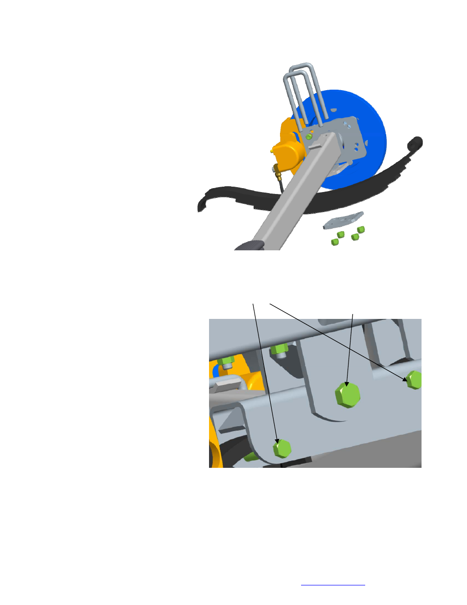
Rocker Bushings & Installation:
Install the 3/4” ID X 1” OD X 1-1/2”
bronze bushings into the rocker. Note
there is a grease zerk in the center
bushing of the rocker bogie. This is
necessary so that it can be serviced in
the field when needed. Position the
rocker bogie into the center mounting
channel of the spring bracket. The
rocker must be positioned with the hole
locations as shown for proper
operation. Align the center hole of the
rocker with the hole in the center
mounting channel of the spring bracket.
Insert a 3/4” x 5-1/2” stainless steel hex
bolt from the outside inward as shown
and secure with a 3/4” stainless steel hex lock nut. Tighten. Repeat on the other rocker bogie
or bogies.
3/4” X 5 1/2”
Stainless Steel
Hex Bolt
Note bolt positions
Midwest Industries, Inc. Ida Grove, IA 51445 800-859-3028
www.shorelandr.com
0004307
Page
4
of
16
2/24/2011