ShoreLand'r SLR95TAL User Manual
Page 14
Midwest Industries, Inc. Ida Grove, IA 51445 800-859-3028
www.shorelandr.com
0004307
Page
14
of
16
2/24/2011
weldment. Secure with one (1) 1/4” X 3/4” stainless steel carriage bolt and one (1) 1/4”
stainless steel hex nut. Plug wiring that was ran through the bunk bracket weldment into the
taillight wire plug. Repeat this same procedure for the right taillight (does not include license
plate bracket).
Front Roller:
Mount the roller arm tube into the pivot base weldment using a 5/8” X 4-1/2” stainless steel hex
head bolt and secure with 5/8” stainless steel hex lock nut with nylon insert. Mount the roller
arm assemblies to roller arm tube with (2) 1/2” X 4-1/2” stainless steel hex head bolts and
securing with (2) 1/2” stainless steel hex lock nuts with nylon inserts.
Repeat on other side.
Rear Roller:
Mount the rear roller arm weldments into the pivot base weldment using 5/8” X 4-1/2 stainless
steel hex bolt and securing with a 5/8” stainless steel lock nut with nylon insert. Mount the
roller arm assemblies to roller arm tube with (2) 1/2” X 4-1/2” stainless steel hex head bolt and
securing with (2) 1/2” stainless steel lock nuts with nylon inserts.
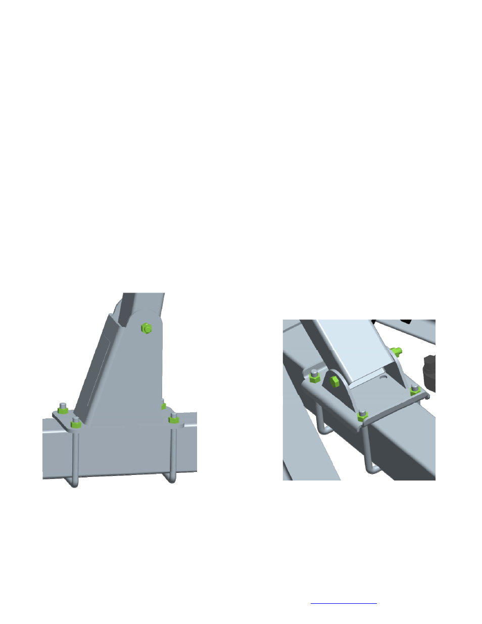
Winch Assembly:
The winch post assembly comes factory assembled and ready to mount on the tongue.
Position the winch assembly on the tongue in a location
that would best fit your watercraft. Using four (4) 5/8” X
5-3/4” X 6-3/4” stainless steel square u-bolts, secure the
winch assembly
to the tongue.
Tighten with 5/8”
stainless steel
lock nuts so that
the winch
assembly will not
slide on tongue.
Refer to winch
adjustments on
page 16.
Brakes:
Refer to the brake manual for service and maintenance.
Winch mount front
Winch mount rear