Rectangular pockets in programs – HEIDENHAIN NC 124 User Manual
Page 91
7
Drilling, Milling Cycles and Hole Patterns in Programs
TNC 124
91
Rectangular pockets in programs
The TNC makes it easier to clear out rectangular pockets. You
need only enter the dimensions of the pocket; the TNC calculates
the tool path for you.
Process
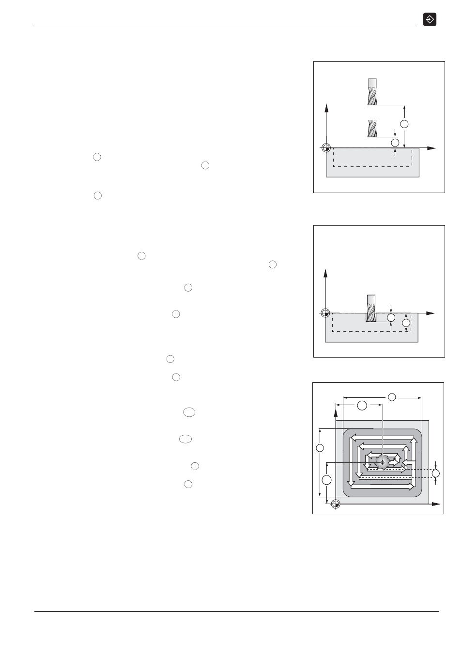
The cycle process is illustrated in Figures 7.6, 7.7 and 7.8.
I
:
The TNC pre-positions the tool in the tool axis at the clearance
height
H
, moves it in the working plane to the pocket center, then
in the tool axis to the setup clearance
A
.
II
:
The TNC drills at the pecking feed rate to the first pecking
depth
C
.
III
:
The TNC clears out the pocket at the milling feed rate along the
path illustrated in Fig. 7.8 below (in this case with climb milling).
IV
:
The pecking and the roughing process are repeated down to the
programmed depth
B
. Then the TNC ends the cycle by moving
the tool in the pocket center back to the clearance height
H
.
Input data for Cycle 4.0 RECTANGULAR POCKET
Clearance height HEIGHT
H
The absolute position in the tool axis at with the tool can move
in the working plane without danger of collision.
Setup clearance DIST
A
The tool moves at rapid traverse from the clearance height to
the setup clearance.
Workpiece surface SURF
Absolute coordinate of the workpiece surface.
Milling depth DEPTH
B
Distance between workpiece surface and bottom of pocket.
Pecking depth PECKG
C
Infeed per drilling cut.
Pecking feed rate F
Tool traversing speed during pecking.
Pocket center in X POSX
MX
Point in the longitudinal axis at which the pocket center is
located.
Pocket center in Y POSY
MY
Point in the transverse axis at which the pocket center is
located.
Side length in X LNGTH X
X
Length of the pocket in the longitudinal axis.
Side length in Y LNGTH Y
Y
Length of the pocket in the transverse axis.
Milling feed rate F
Traversing speed of the tool in the working plane.
Direction DIRCTN
Input value 0: climb milling (Fig. 7.8: clockwise)
Input value 1: upcut milling (counterclockwise)
Finishing allowance - ALLOW
Finishing allowance in the working plane.
Fig. 7.6:
Step I in Cycle
4.0 RECTANGULAR POCKET
I
Z
A
H
X
II
Z
C
B
X
Fig. 7.8:
Step III in Cycle
4.0 RECTANGULAR POCKET
III
MY
R
Y
X
MX
Y
X
Fig. 7.7:
Step II in Cycle
4.0 RECTANGULAR POCKET