Elation Professional 575E User Manual
Page 17
Design Spot 575E™
©Elation Professional® 17
Design Spot 575E™
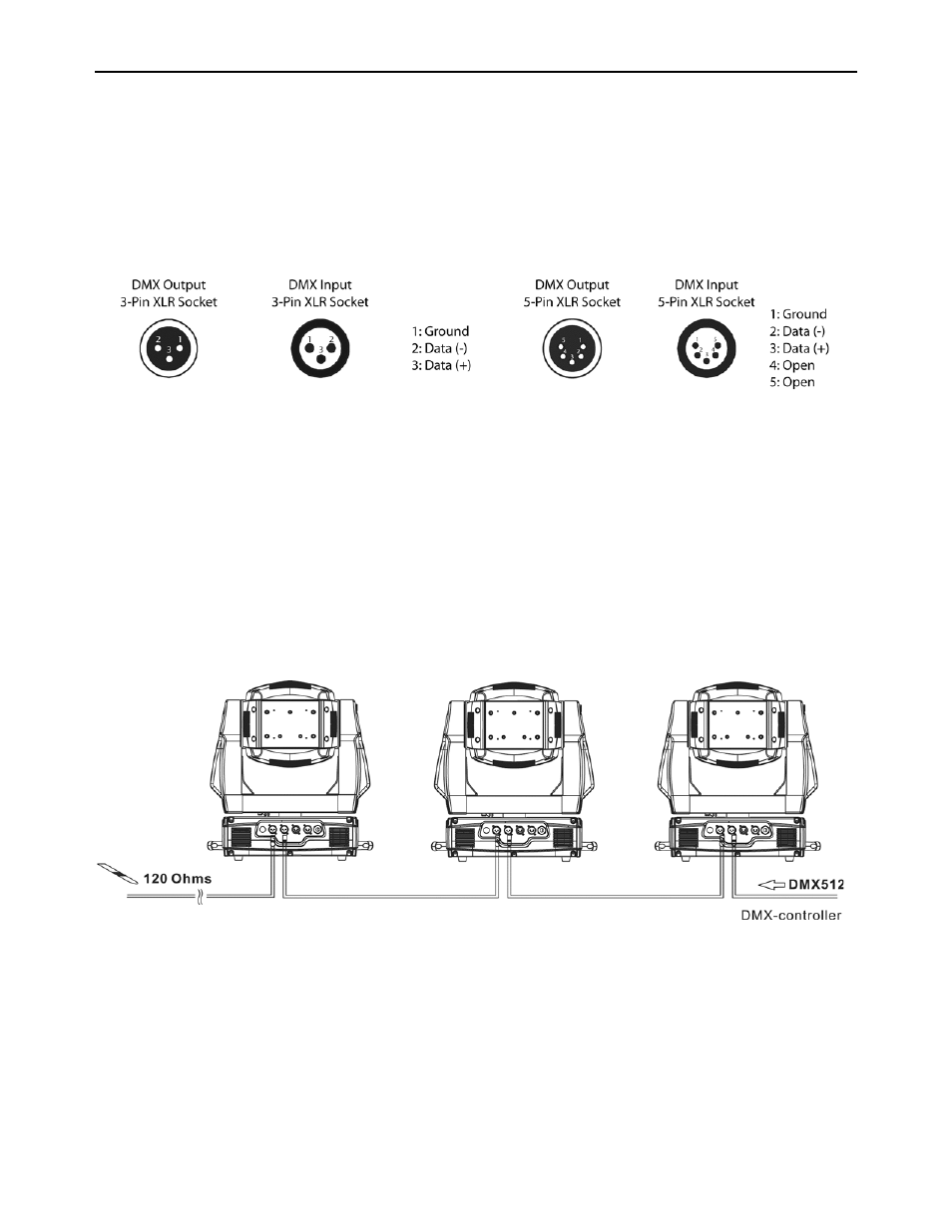
Be sure to follow the pin configuration chart below when making your own cables. Do not
use the ground lug on the XLR connector. Do not connect the cable’s shield conductor to the
ground lug or allow the shield conductor to come in contact with the XLR’s outer casing.
Grounding the shield could cause a short circuit and erratic behavior.
DMX-512 control connection
Connect the provided XLR cable to the female 3-pin XLR output of your controller and the
other side to the male 3-pin XLR input of the moving head (Please refer to the diagram
below.). You can chain multiple moving heads together through serial linking. Always be
sure daisy chain your in and out data connections, never split or “Y” your DMX connections
unless you are using an approved DMX splitter such as the Elation Opto Branch 4™ or DMX
Branch/4™.
DMX-512 connection with DMX terminator
When longer runs of cable are used, you may need to use a terminator on the last fixture to
avoid erratic behavior. A terminator is a 90-120 ohm 1/4 watt resistor that is connected
between pins 2 and 3 of a male XLR connector (DATA + and DATA -). This fixture is inserted
in the female XLR connector of the last fixture in your daisy chain to terminate the line. Using