3 connectors and switches – Grass Valley DCR 4000 User Manual
Page 9
v4.0
DCR 4000 User’s Guide | Installation
1-3
1.3
Connectors and switches
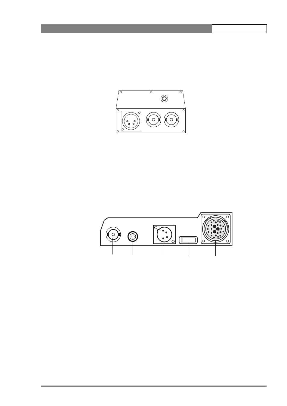
1.3.1
Connectors on Venom
HDSDI A & B : BNC connectors give playback or monitoring outputs according to the format
recorded. When a Dual Link 4:4:4 signal is used, these two connectors give one Dual Link
output. If a single HDSDI (4:2:2) format is recorded, these give two identical outputs.
12V DC: input XLR-4p used when Venom is not mounted on the camera, e.g. for playback.
Audio out: 3.5mm Jack stereo output for two audio channels
1.3.2
Connectors on Docking Adaptor
Genlock: BNC connector. Genlock signal can be either HD Tri-level sync, or Analog Black
reference. The genlock signal must be of the same format as that selected on the camera.
Timecode: Standard 5-pin Lemo LTC connector for external time code signal (input + output).
DC Input: XLR 4 pin connector for 12V DC input.
Multicore connector: 26 pin connection for cable to Viper camera.
AUDIO OUT
12 V DC
HDSDI A -> HDSDI B ->
Genlock
LTC
connector
DC input
Power
On/OFF
Multicore
connector