Grass Valley DHP v.1.1 User Manual
Page 20
12
DHP Service
Configuration Process
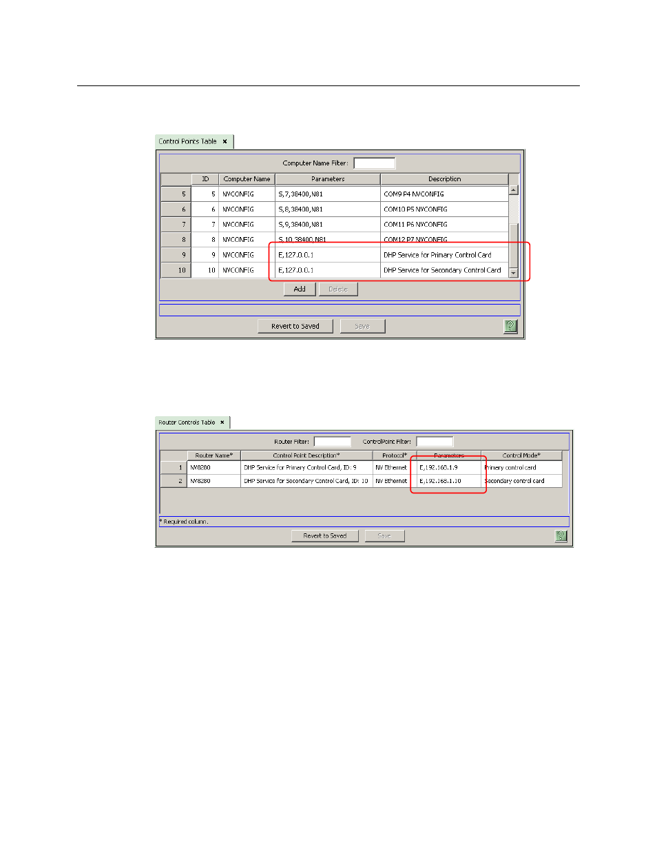
Then, in the ‘Control Points’ table (under the ‘Views’ navigation pane), change the description
field for the DHP proxy of the router: This is a sample control point table (for an NV8280):
Changing the description is not actually necessary, but very helpful.
If you are modifying an existing router definition, it is here that you would change its IP address
to 127.0.0.1.
Then, update the parameters fields in the ‘Router Controls’ table:
Define the parameters field as “E”, comma, and the IP address of the router control card. Doing
that lets the DHP service know the IP address of the router control card with which it is to
communicate.
(If you are modifying an existing router definition, the values you enter in the parameters field
here are what were in the parameters field of the control points table. These IP addresses will
have been initially defined in MRC.)
When there are two control cards, one primary and one secondary, only one of those control
cards is actively running. The other control card is in stand-by mode.
Similarly, when there are two control cards, the NV9000 will launch two DHP services at startup.
One of the DHP services is active and the other is stand-by (running, but idle).
At this stage, the ‘Control Points’ table is not quite finished
—
you must specify the DHP ports.