Grass Valley KAM-DEC-2AES v.4.0.3 User Manual
Page 29
KAM-DEC-2AES Instruction Manual
29
KAM-DEC-2AES Links and Web Pages
Header Row
The top header row provides the connector hardware physical label (J#)
and the dedicated signal type for the connector. This information is deter-
mined by the type of rear module and front processor module installed
(refer to the
Functional View Web Page on page 30
Connectors
The connector row illustrates connector type provided (BNC or 3-pin ter-
minal) for each port. For this rear module, one component video input, two
balanced or unbalanced AES audio inputs, and one serial digital output are
provided.
Input/Output Mode
I/O mode is either static read-only or an operational Input/Output selec-
tion (determined by the rear module used).
Signal Name
Enter a signal name (up to 15 characters) for each operational
input/output. The name will be used to identify the signal in other config-
uration web pages. Factory default names are shown in
.
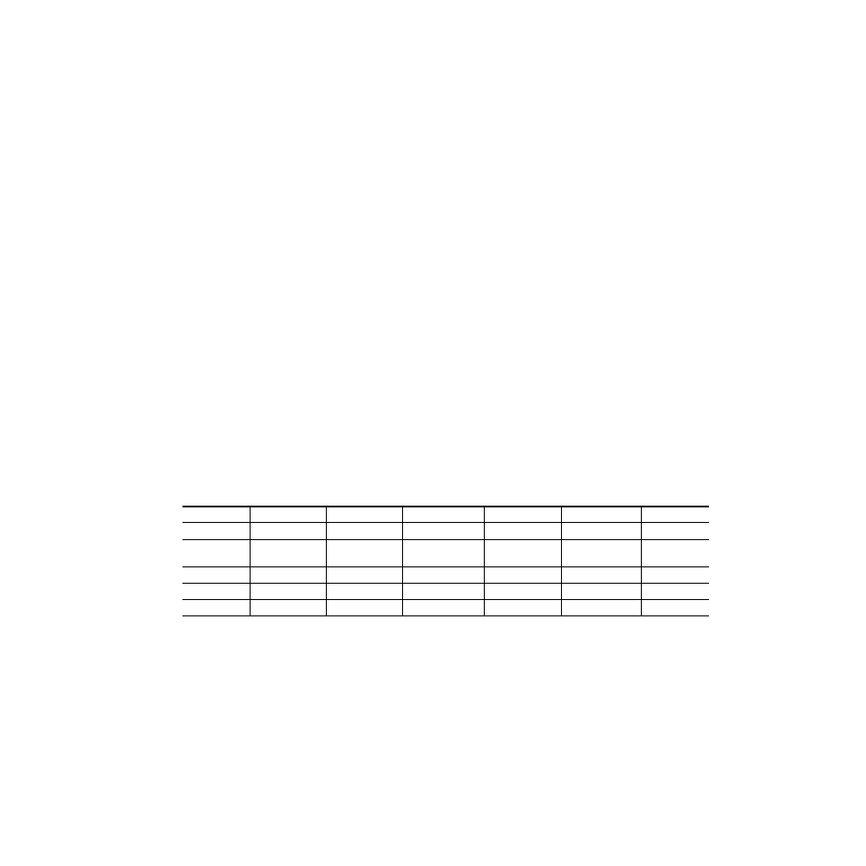
Status
shows, by color and signal type, the signal status reports that may
be displayed in the Status row for this module configuration:
Table 4. I/O Config Status Report Messages
Color
Video In
Analog Audio In
Analog Audio Out
Digital Audio In
Digital Audio Out
Video Out
Green
Present
None
None
Present
None
None
Yellow
Not present or
525/625 mismatch
None
None
Not Present
None
None
Light Grey
None
None
None
None
Not Monitored
Not Monitored
Medium Grey
None
None
None
Not Available
Not Available
None
Dark Grey
None
None
None
None
None
None
- KAM-DEC-2AES-MUX v.1.0.4 KAM-DEC-4ADC v.4.0.3 Kameleon Series v.5.1.0 Kameleon Series v.6.0.2 Kameleon Series v.4.1.0 KAM-DEC-4ADC-MUX v.1.0.4 KAM-DEC-4ADC-MUX v.5.0.2 KAM-SD-2AES v.4.0.3 KAM-ENC-4DAC v.4.0.1 KAM-ENC-2AES v.4.0.1 KAM-ENC-2AES-DMX v.1.0.4 KAM-ENC-4DAC-DMX v.1.0.4 KAM-SD-4DAC-DMX v.4.0.1 KAM-SD-2AES-MUX v.4.0.1 KAM-SD-2AES-EAP v.4.0.1 KAM-SD-2AES-DMX v.1.0.4