Cable channelflex suite inputs and outputs, Cabling systems, C1 c2 – Grass Valley K2 Dyno Installation v.2.0 User Manual
Page 19
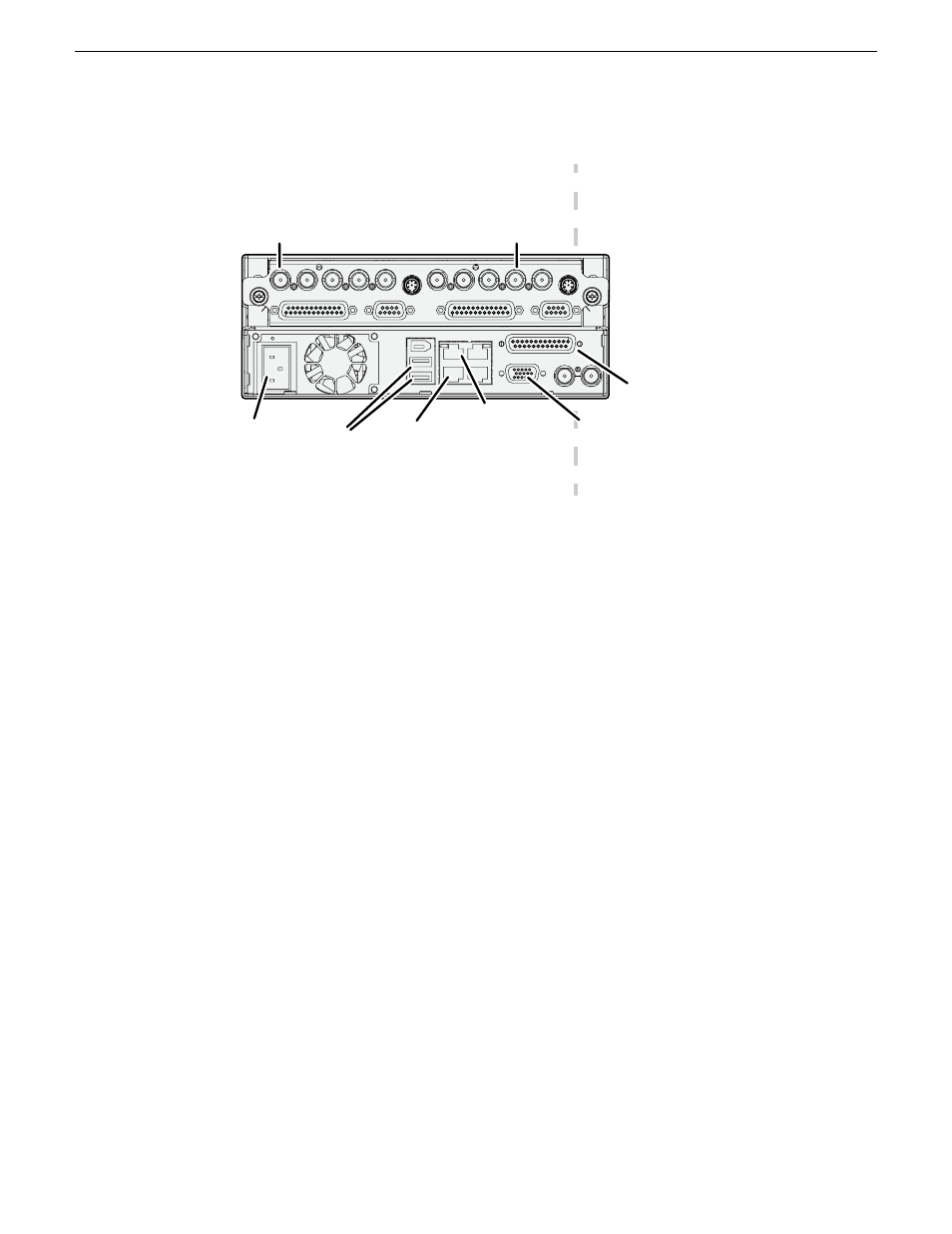
2. Make cable connections. Connections for a typical system are illustrated.
C1
C2
USB/139
4
100-240 V-
4-2A,
60-50Hz
100BT/1000B
T
GPI
VGA
REF. LOOP THROUG
H
SDI IN
1
SDI OUT
1
SDI OUT2
LTC I/O
AESAUDI
O
RS422
SDI OUT1 SDI OUT2
AESAUDI
O
RS422
LTC I/O
SDI IN
2
SDI IN
3
SDI IN
1
SDI IN
2
SDI IN3
Channels (C1, C2) are bi-directional
Use C1 as
record channel.
Connect SDI in
Use C2 as
play channel.
Connect SDI out
Power
cord
AES
audio
Keyboard
and mouse
VGA
monitor
Ethernet
control
connection
Optional:
Ethernet
media
(FTP)
connection
Each channel can be both an input (record channel) and an output (play channel). For the typical
system, C1 is a record channel and C2 is a play channel.
The control connection between the K2 Summit Client and the K2 Dyno Controller can be via
direct connect cable or via an Ethernet switch. Control connections must be on the same network
(subnet).
For complete cabling instructions, refer to the K2 System Guide. If using ChannelFlex Suite features,
refer to the K2 AppCenter User Manual.
Cable ChannelFlex Suite inputs and outputs
ChannelFlex Suite features require the AppCenter Elite license. Super Slo-Mo also requires the HD
license. When the K2 Summit Production Client or K2 Solo Media Server is licensed and configured
for these features, channel connections are as follows:
14June 2011
K2 Dyno Controller Installation Manual
19
Cabling systems