Grass Valley AMX-3981 2014 User Manual
Page 13
GUIDE TO INSTALLATION AND OPERATION
AMX-3981 | 7
Rear Panel Type
Connector(s) / Impedance
AMX-3981-110-3DRP-F
D-SUB 26
(1)
110
Ω
AMX-3981-110-3SRP
D-SUB 26
(1)
110
Ω
AMX-3981-75-3DRP-F
BNC
(8)
75
Ω
AMX-3981-75D-3SRP
DIN 1.0/2.3 (8)
75
Ω
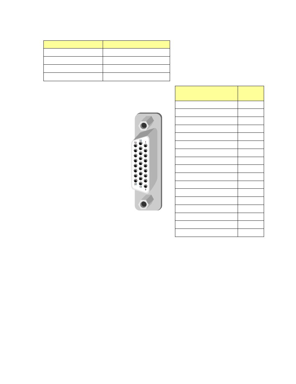
The pinout of the D-SUB connector for both 110
Ω rear panels is
shown in this chart.
Fiber I/O – Fiber-optic inputs and outputs
Rear panels whose part number ends in –F incorporate a fiber optic interface. The interface consists of two parts:
• A socket on the rear panel into which an SFP interface module is plugged
• An SFP (Small Form-factor Pluggable) module into which the optical fibers are plugged, and which incorporates
the optical/electrical interface
The optical fibers must be terminated in an LC connector.
See Annex 3 for instructions on installing and removing the SFP interface module, and for plugging and unplugging
the LC-terminated fibers.
The SFP modules supported by the AMX-3981 are:
AMX-3981-110-3SRP
AMX-3981-110-3DRP-F
Pin #
AES IN 1 (Hi)
1
AES IN 1 (Lo)
10
AES IN 2 (Hi)
2
AES IN 2 (Lo)
11
AES IN 3 (Hi)
3
AES IN 3 (Lo)
12
AES IN 4 (Hi)
4
AES IN 4 (Lo)
13
AES IN 5 (Hi)
5
AES IN 5 (Lo)
14
AES IN 6 (Hi)
6
AES IN 6 (Lo)
15
AES IN 7 (Hi)
7
AES IN 7 (Lo)
16
AES IN 8 (Hi)
8
AES IN 8 (Lo)
17
GND
9, 18-26