Service, Power-up diagnostic failure, Troubleshooting – Grass Valley 8964DEC v.1.1.0 User Manual
Page 65: Refer to
8964DEC/-FS — Instruction Manual
65
Service
Service
The 8964DEC modules make extensive use of surface-mount technology
and programmed parts to achieve compact size and adherence to
demanding technical specifications. Circuit modules should not be ser-
viced in the field unless directed otherwise by Customer Service.
Power-Up Diagnostic Failure
If the module has not passed self-diagnostics, do not attempt to trouble-
shoot. Return the unit to Grass Valley (see
below).
Troubleshooting
If your module is not operating correctly, proceed as follows:
•
Check frame and module power and signal present LEDs.
•
Verify power at the voltage testpoints (see
) and check Fuse F1
if no voltage is detected.
•
Check for presence and quality of input signals.
•
Verify that source equipment is operating correctly.
•
Check cable connections.
•
Check output connections for correct I/O mapping (correct input con-
nector is used for the corresponding channel output).
for the location of PWR LED and
for proper LED indications.
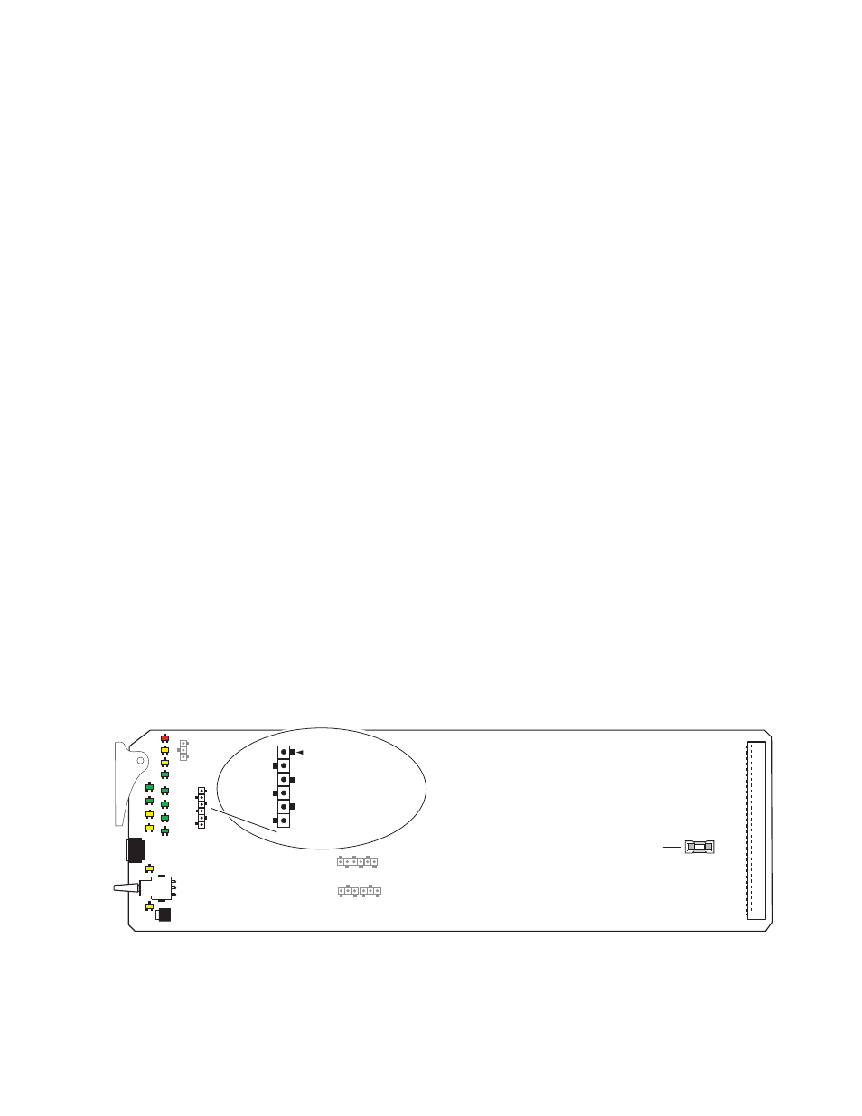
Figure 33. 8964DEC Fuse and Voltage Testpoints Locations
8208_08
r1
Voltage Testpoints
J1
+5V
–5V
+3.3V
+1.5V
Fuse: 2 A Slow
125 V
F1