Refer to – Grass Valley 8964DEC v.1.1.0 User Manual
Page 27
8964DEC/-FS — Instruction Manual
27
Configuration
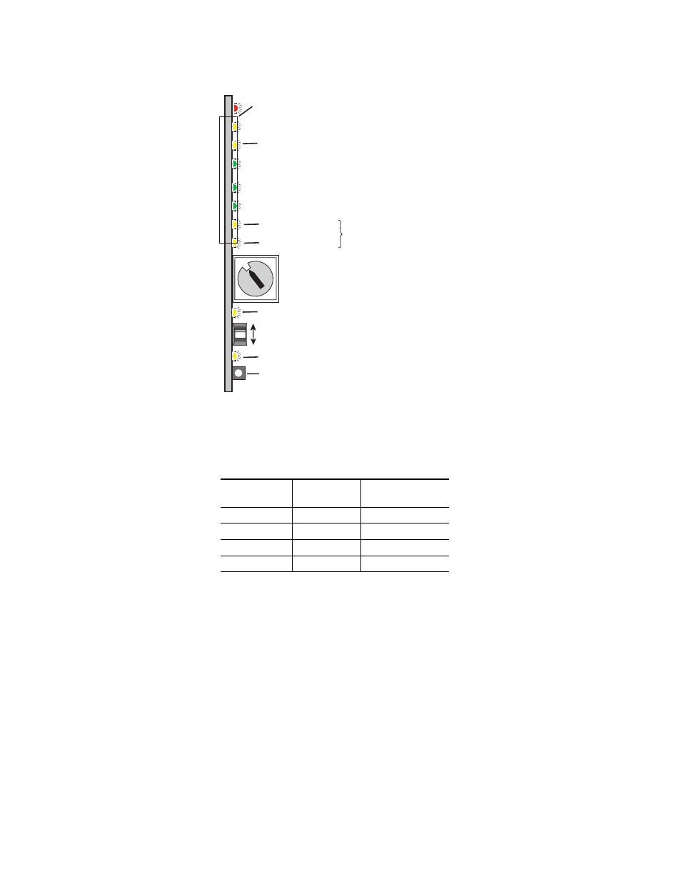
Figure 8. Onboard Configuration Components – Front View
for reading the CM1 and CM0 active channel LED indica-
tors.
Table 5. CM1 and CM0 LED Table
CM1 LED State
CM0 LED
State
Channel Control
Off
Off
Channel 1 is active
Off
On
Channel 2 is active
On
Off
Channel 3 is active
On
On
Channel 4 is active
SW1 16-position Function rotary switch – accesses 3 banks of
controls. Bank selected is indicted by state of 2ND LED.
SW4 Paddle switch for incrementing parameter values (Parameter mode)
or selecting active channel (CSM, Channel Select Mode)
SW2 – Pushbutton switch to toggle between Parameter
and CSM modes
Ejector Tab
2ND LED – Bank 1 = Off , Bank 2 = On, Bank 3 = flashing
8208_07
r1
0
1
2
3 4
5 6 7
8
9
A
B
CD
E
F
CONF – Yellow LED on indicates module is initiating,
changing operating mode, or updating firmware
CM1 – Yellow LED
CSM LED – on in Channel Select Mode (use paddle to select channel)
CM0 – Yellow LED
Indicate active channel control (see table in text)
- LDK 5302 (24 pages)
- SFP Optical Converters (18 pages)
- 2000GEN (22 pages)
- 2011RDA (28 pages)
- 2010RDA-16 (28 pages)
- 2000NET v3.2.2 (72 pages)
- 2000NET v3.1 (68 pages)
- 2020DAC D-To-A (30 pages)
- 2000NET v4.0.0 (92 pages)
- 2020ADC A-To-D (32 pages)
- 2030RDA (36 pages)
- 2031RDA-SM (38 pages)
- 2041EDA (20 pages)
- 2040RDA (24 pages)
- 2041RDA (24 pages)
- 2042EDA (26 pages)
- 2090MDC (30 pages)
- 2040RDA-FR (52 pages)
- LDK 4021 (22 pages)
- 3DX-3901 (38 pages)
- LDK 4420 (82 pages)
- LDK 5307 (40 pages)
- Maestro Master Control Installation v.1.5.1 (428 pages)
- Maestro Master Control Installation v.1.5.1 (455 pages)
- 7600REF Installation (16 pages)
- 7600REF (84 pages)
- 8900FSS (18 pages)
- 8900GEN-SM (50 pages)
- 8900NET v.4.3.0 (108 pages)
- Safety Summary (17 pages)
- 8900NET v.4.0.0 (94 pages)
- 8906 (34 pages)
- 8911 (16 pages)
- 8900NET v.3.2.2 (78 pages)
- 8914 (18 pages)
- 8912RDA-D (20 pages)
- 8916 (26 pages)
- 8910ADA-SR (58 pages)
- 8920ADC v.2.0 (28 pages)
- 8920ADC v.2.0.1A (40 pages)
- 8920DAC (28 pages)
- 8920DMX (30 pages)
- 8920ADT (36 pages)
- 8920MUX (50 pages)
- 8921ADT (58 pages)