T2) should be on. refer to, To see a complete list of possible – Grass Valley 8949MDA-CFR v.1.0.X User Manual
Page 17
8949MDA-CFR and 8949MDA-SFR Instruction Manual
17
Power Up
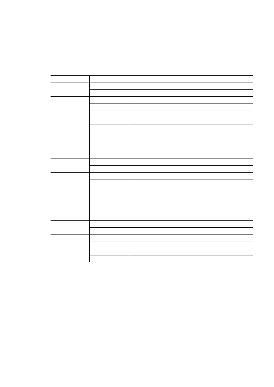
A red FAULT LED indicates an error situation and, when noted with the other indi-
cator LEDs, can indicate a specific problem area.
describes signal output
and LED indications for the various input/reference combinations.
Table 5. LED Indicators
LED
Indication
Condition
FAULT (red)
Off Normal
operation
On continuously Module
has detected internal fault
COMM (yellow)
Off No
activity on frame communication bus
Long flash
Location Command received by the module from a remote control system
Short flash
Activity present on the frame communication bus
CONFIG (yellow)
Off Module
is in normal operating mode
On continuously
Module is initializing, changing operating modes or updating firmware
PWR (green)
Off
No power to module or module’s DC/DC converter failed
On continuously
Normal operation, module is powered
PRES OPT MOD
(yellow)
Off
Fiber optic submodule not installed
On
Fiber optic submodule installed
COMPOSITE SETUP
(yellow)
Off
Setup disabled
On
Setup enabled
FACTORY
(yellow)
Off
Normal operation
On
Test mode or factory mode
MONITORING MODE
(Channel 1
F0, F1, F2 and F3)
(yellow)
0000 --> Auto
0001 --> 1080i/50
0010 --> 1080i/59.94
0011 --> 720p/50
0100 --> 720p/59.94
0101 --> 480i/59.94
0110 --> 576i/50
PRES SIG EQ
(green)
Off
No presence of signal on BNC (on J9 connector)
On continuously
Presence of signal on BNC (on J9 connector)
PRES SIG OPT 1
(green)
Off
No presence of optical signal on opt 1
On continuously
Presence of optical signal on opt1
PRES SIG OPT 2
(green)
Off
No presence of optical signal on opt 2
On continuously
Presence of optical signal on opt 2