8737d module, Looping capabilities – Grass Valley 8937 v.1.1.0 User Manual
Page 16
16
8937/8937D — Instruction Manual
Installation
8737D Module
for cabling the 8937D module. Cabling to and from the
module is done at the back of the Gecko 8900 video frame or on the corre-
sponding 8900V-R rear module on the GeckoFlex frame as described below.
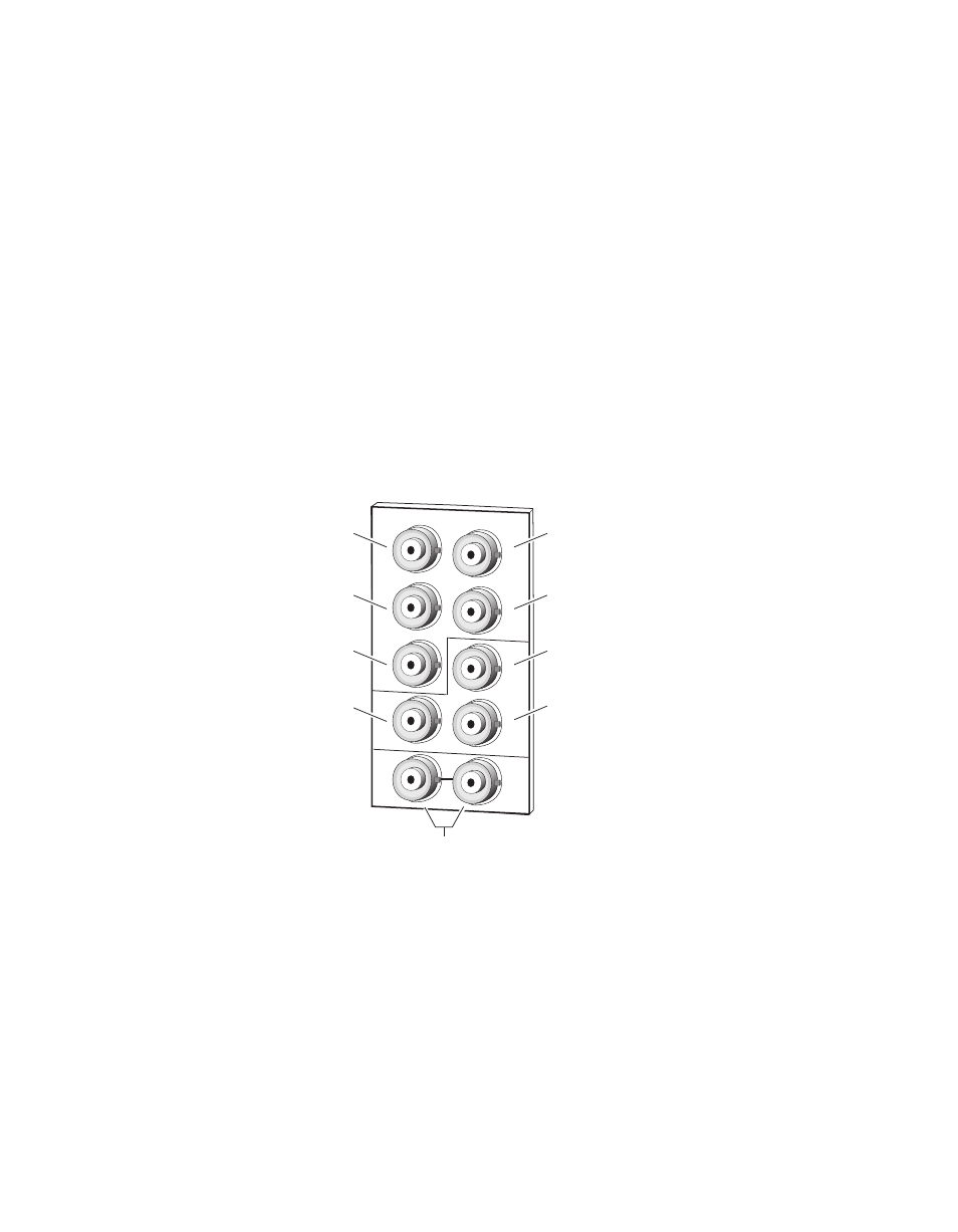
DA 1 Inputs and Outputs
DA 1 provides one serial digital component input at loop-through BNCs J9
and J10. If the unused input is not looped to another device, it should be ter-
minated in 75 ohm. The three outputs for DA 1 are from BNCs J6, J7, and
J8. All outputs are in phase with the input signal.
DA 2 Inputs and Outputs
DA 2 provides one terminated serial digital component input at BNC J5.
The four outputs for DA 2 are from BNCs J1, J2, J3, and J4. All outputs are
in phase with the input signal.
Figure 6. 8937D Rear Input/Output Connectors
Looping Capabilities
The reclocked output signal from one 8937 or 8937D module may be looped
to up to ten reclocked 8937 or 8937D modules in series for further distribu-
tion without degrading the signal.
The output signal from modules operating in Bypass mode (not reclocked
to one of the standard rates) will begin to degrade by the third module in
the series. This looping is not recommended.
J2
J4
J6
J8
Out 1-3
8270_09
r1
SDI In 1
(differential loop-through)
Out 2-1
SDI In 2
(terminated)
Out 2-3
Out 2-2
Out 2-4
Out 1-1
Out 1-2
J9
J10
J3
J5
J7
J2
J1
J4
J6
J8