Fer to, Press in the ejector tab to seat the module – Grass Valley 8937 v.1.1.0 User Manual
Page 11
8937/8937D — Instruction Manual
11
Installation
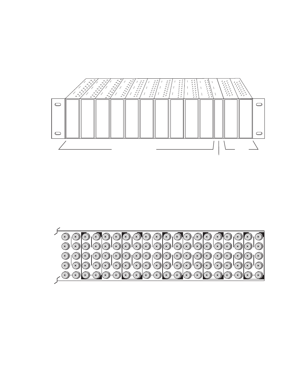
The third slot from the right is allocated for either a Frame Monitor Module
or a 8900NET (Net Card) Network Interface Module. For additional infor-
mation concerning the controller module options, refer to the 8900NET (Net
Card) Network Interface Module Instruction Manual.
Figure 1. 8900 Series Video Frame Slots
8900 module slots are interchangeable within the frame. There are 10 BNCs
in each slot’s I/O group. The functional assignment of each connector in a
group is determined by the module that is placed in that slot. The
maximum number of modules a Gecko 8900 video frame can accept is ten.
illustrates the rear connector plate for a Gecko 8900 video frame.
Figure 2. Gecko 8900 Series Video Frame Rear Connector
To install a module in the frame:
1.
Insert the module, connector end first, with the component side of the
module facing to the right and the ejector tab to the top.
2.
Verify that the module connector seats properly against the backplane.
3.
Press in the ejector tab to seat the module.
Frame Monitor or
8900NET Network
Interface Module
Any Gecko/8900 Module
Power
Supplies
8270_02
r1
8270_01
J1
J2
J3
J4
J5
J6
J7
J8
J9 J10
IN
DA1
J2
J4
J6
J8
J1
J2
J3
J4
J5
J6
J7
J8
J9 J10
IN
DA3
J1
J2
J3
J4
J5
J6
J7
J8
J9 J10
IN
DA5
J1
J2
J3
J4
J5
J6
J7
J8
J9 J10
IN
DA2
J1
J2
J3
J4
J5
J6
J7
J8
J9 J10
IN
DA7
J1
J2
J3
J4
J5
J6
J7
J8
J9 J10
IN
DA9
J1
J2
J3
J4
J5
J6
J7
J8
J9 J10
IN
DA4
J2
J4
J6
J8
J1
J2
J3
J4
J5
J6
J7
J8
J9 J10
IN
DA6
J2
J4
J6
J8
J1
J2
J3
J4
J5
J6
J7
J8
J9 J10
IN
DA8
J2
J4
J6
J8
J1
J2
J3
J4
J5
J6
J7
J8
J9 J10
IN
DA10
O
U
T
O
U
T
O
U
T
O
U
T
O
U
T
O
U
T
O
U
T
O
U
T
O
U
T
O
U
T