Installation, Module on-board jumper settings – Grass Valley 8921DAC User Manual
Page 8
8
8921DAC Instruction Manual
Installation
Installation
Installation of the 8921DAC module is a process of:
1.
Setting on-board jumpers for desired input formats,
2.
Placing the module in the proper audio frame slot, and
3.
Cabling and terminating signal ports.
The 8921DAC module can be plugged in and removed from a Gecko 8900
audio frame with power on. When power is applied to the module, LED
indicators reflect the initialization process (see
).
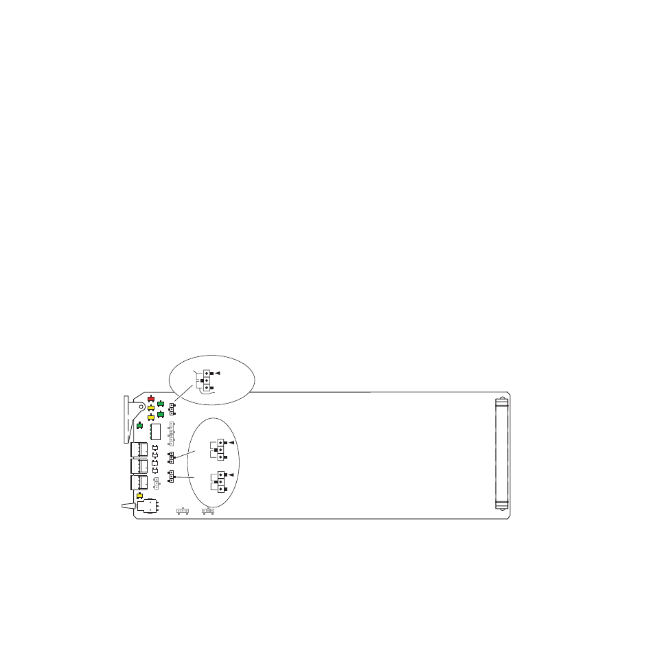
Module On-board Jumper Settings
The on-board jumpers shown in
must be set for the following:
•
Local/Remote operation – set jumper J2 to LOC (pins 1-2) to lock out
remote control or LOC/REM (pins 2-3) for both local and remote con-
trol.
•
AES 1 and AES 2 input format – the input format for AES 1 and AES 2
must be set to either balanced (pins 2-3) or unbalanced (pins 1-2) with
jumpers J9 (AES 2 – IN) and J10 (AES 1 – IN) depending on the input
format desired.
Figure 1. On-Board Jumper Locations
J10
J9
J2
8214_04
J2
Set jumper J2 to
LOC (1-2) local only, remote lockout
or LOC/REM (2-3) local and remote.
LOC
LOC/REM
Set jumpers J9 and J10
to UNBAL (1-2) unbalanced or
BAL (2-3) balanced to
match input format.
J10
J9
UNBAL
BAL
AES 1 – IN
AES 2 – IN
UNBAL
BAL