Gpi output jumpers – Ensemble Designs 9455 3G Clean and Quiet Protection Switch User Manual
Page 33
www.ensembledesigns.com
7435 and 9455 - page 33
Model 7435 and 9455 Clean and Quiet Protection Switches
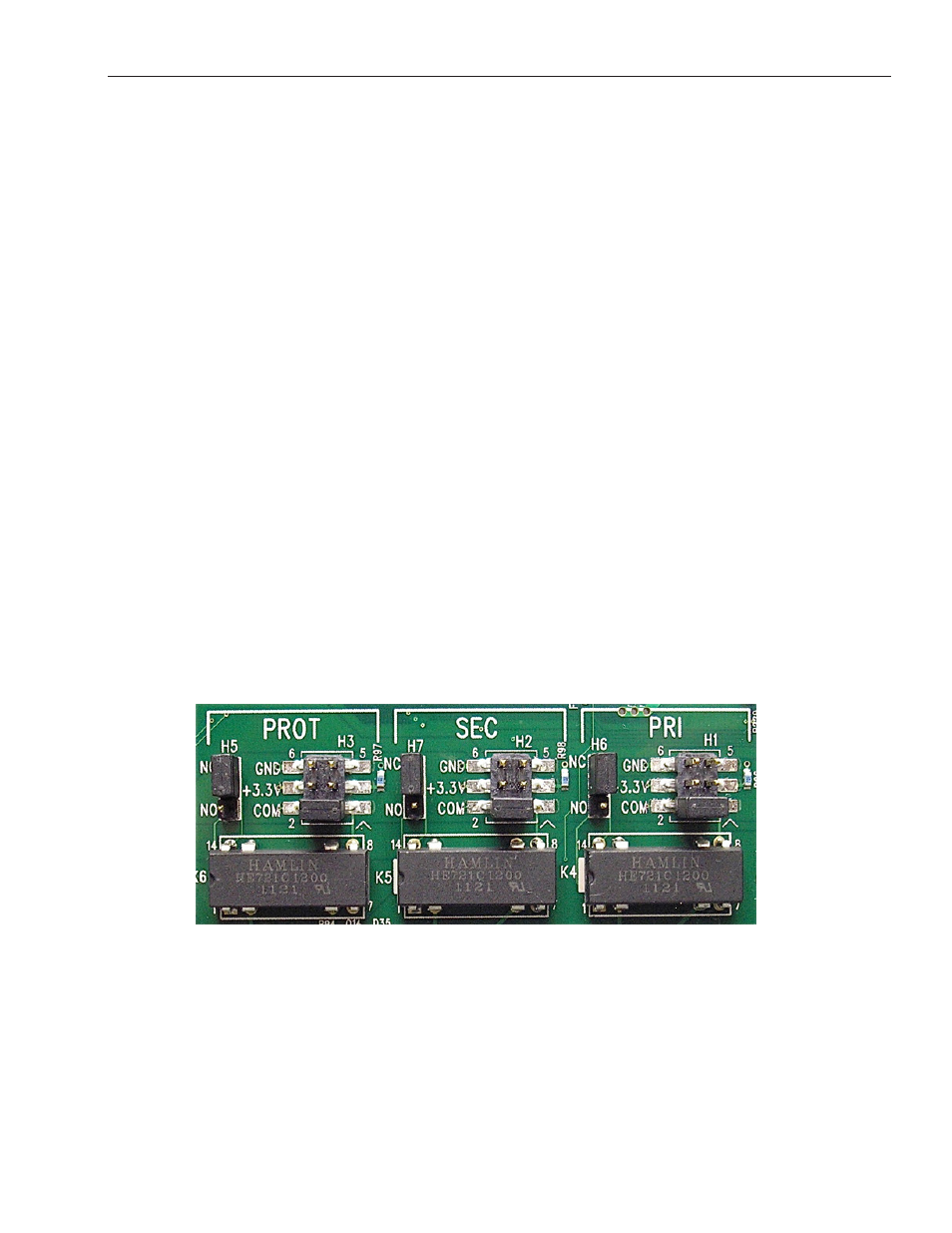
Close up of relay section and associated jumpers on the 9455 module
GPI Output Jumpers
The GPI outputs for the Primary, Secondary and Switch Position are controlled by a series of relays and
jumpers on the module.
The relay contacts provide both NO (Normally Open) and NC (Normally Closed) switching to indicate
fault status of the Primary and Secondary inputs, and the Protection Switch output. Normally Closed
indicates that the signal is good. Select Normally Open (NO) or Normally Closed (NC) via the
2 position headers; H5, H6 and H7 (see illustration below, and details on the following page).
An individual common is provided to each of the relays. For each of the three status relays there is a 3
position header which configures the common signal that will be used by that relay. Each GPI output is
independently strappable to provide Ground, current limited +3.3V (1k resistor), or a Common. Select
Gorund, +3.3 volts or Common via the 3 position headers; H1, H2 and H3 (see illustration below, and
details on the following page).
As an example, with jumpers for the Primary set to NC and +3.3V, the Primary Contact output
(pin 6 of the 9 pin D connector) will source +3.3 volts when the relay is in the normal position,
closed (Signal Good). If the signal fails, the output will be open.
Additionally, in the case of selecting +3.3V as the common, the 1k resistor on the module will act as a
current limiter, allowing the direct connection of ordinary LEDs to each of the output pins. A green
LED could be connected to the Primary Contact output and a red LED to the Protection Contact
output. This would provide complete and explicit indication to the operator as to the signal status and
switch position.