Ensemble Designs 7900 HD Up/Down/Cross Converter User Manual
Page 8
INSTALLATION
Submodule Installation
An optional audio submodule installs on the component side of the 7900 module circuit
board. If the option is ordered with the 7900 module, it will come already installed.
To install an audio submodule, locate the three connectors on the left side of the circuit
board as shown below and line the connectors up, checking the alignment. Press carefully
into place to seat the submodule.
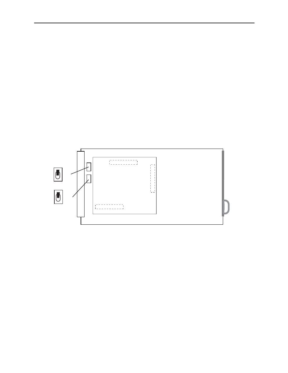
SD or Composite Out BNC Configuration
Two of the four SD Out BNCs can be configured as either serial or composite outputs by
setting switches S3 (HD/SD Out 3 Cspt Out BNC) or S4 (HD/SD Out 4 Cpst Out
BNC). Refer to the illustration below for the locations of the switches on the rear of the
circuit board. Set each switch independently to the up position for CPST and the down
position for SER.
7900 Video Processing Module
Plug the 7900 module into any one of the slots in the 1 RU or 3 RU Avenue frame and
install the plastic overlay provided onto the corresponding group of rear BNC connectors
associated with the module location.
Note that the plastic overlay has an optional adhesive backing for securing it to the
frame. Use of the adhesive backing is only necessary if you would like the location to be
permanent and is not recommended if you need to change module locations. This module
may be hot-swapped (inserted or removed) without powering down or disturbing perfor-
mance of the other modules in the system.
CABLING
Refer to the 3 RU and 1 RU backplane diagrams of the module below for cabling
instructions. Note that unless stated otherwise, the 1 RU cabling explanations are identi-
cal to those given in the 3 RU diagram.
Model 7900 HD Up/Down/Cross Converter
7900-8
8415 Audio Processor
CPST
SER
CPST
SER
Set toggle switches to configure BNCs on the rear module.
S3 CPST or SER on BNC labeled HD/SD Out 3 Cpst Out
S4 CPST or SER on BNC labeled HD/SD Out 4 Cpst Out
S3
S4
Audio Submodule Installation and BNC Configuration