Ensemble Designs 7160 Serial Digital Protection DA User Manual
Page 7
www.ensembledesigns.com
7160-7
Model 7160 HD/SD/ASI/310 Protection DA
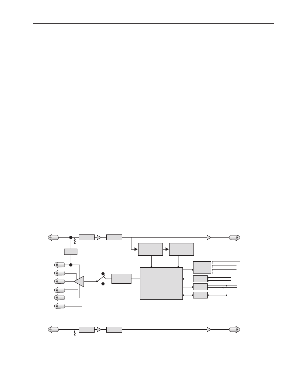
Each of the signals is fed to identical detection circuits which evaluate multiple parameters and
characteristics of the signal in order to arrive at a fault decision. Detection of TRS errors is done in a
Receiver/Reclocker circuit which produces a reclocked serial output feeding a Deserializer circuit. The
output of this section then feeds a Field Programmable Gate Array (FPGA) where the signals are vetted,
or tested for configured parameters. The Signal Vetter™ process in the FPGA detects the parameters
chosen by the user using either the front panel controls or through the Avenue PC or Touch Screen
menus. Each of the chosen aspects are monitored independently, and when they fail to meet the
vetted standard, a fault condition is issued. Fault conditions can be monitored with an external alarm
system or other device through the 15-pin Control connector on the corresponding rear backplane
connector. The Form C relays status outputs from this connector can be monitored by a device to
show Primary and Secondary signal status and the current position of the protect switch (Primary or
Secondary).
Two GPI Override Inputs are available to allow changing switch position in response to triggers from
an external source. This can be used to manually reset the switch after the Primary has recovered from
a fault condition or set to respond to a signal state from an external device to trigger a switch.
The on-board CPU can monitor and report module ID information (slot location, software version
and board revision), and power status to the optional frame System Control module. This information
can be accessed by the user or set to register an alarm if desired using the remote control options
available.
Every function and parameter on the module can be controlled from an Avenue Touch Screen Control
Panel or the Avenue PC Control Application. Memory registers can be used to save the complete
configuration of the module, making it easy to change instantly between different configurations.
Modules at software version 2.2.0 or later support SNMP (Simple Network Management Protocol)
monitoring. For each applicable signal processing module, module, signal, and reference status are
reported. For complete details on using SNMP monitoring, refer to the Avenue System Overview in the
manual that accompanies each frame.
7160 HD/SD/ASI/310 Protection DA, portrait layout
Rcvr/EQ
Deserializer
& EDH Processor
Primary
Loopback
Content
Analyzer
Protection
Watchdog
GPI Inputs
Sel Sec
Sel Pri
Switch Position
GPI Override Inputs
Status Logging
Avenue System Control
Secondary Fail
Primary Fail
Common
Serial Port
Form C
Relay
Alarm Outputs
Backplane
Interface
Module Control System
Decision Arbitration
Reclocker
Relay
Rcvr/EQ
Secondary
Loopback
HD/SD
Primary Input
Relay
Protected
Output
(Fail-safe)
Protected
Outputs
(5 each)
HD/SD
Secondary Input
Reclocker