3ru and 1ru backplane diagrams, 3ru backplane 1ru backplane – Ensemble Designs 7160 Serial Digital Protection DA User Manual
Page 11
www.ensembledesigns.com
7160-11
Model 7160 HD/SD/ASI/310 Protection DA
7160 PDA
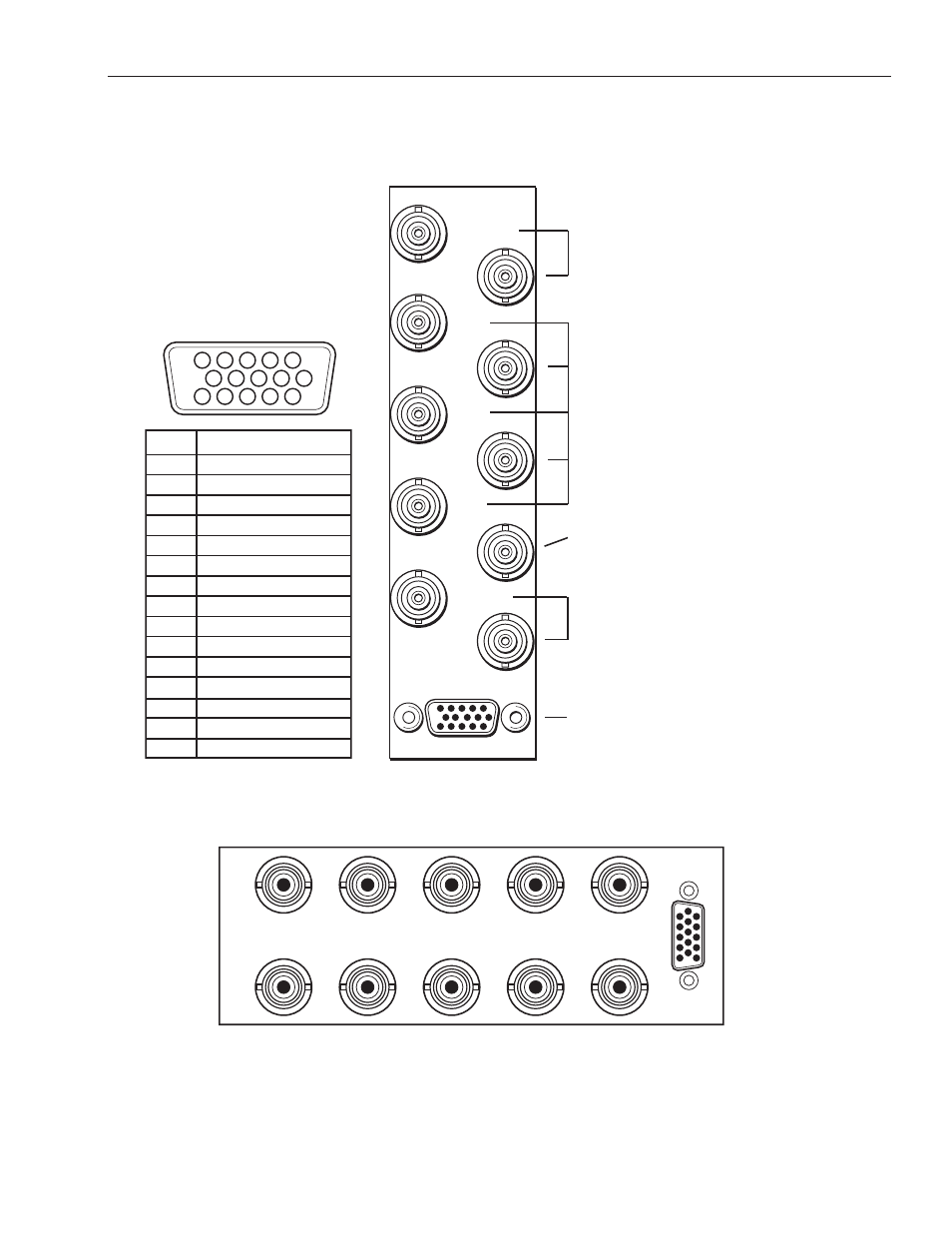
Secondary In
Sec Loop Out
Out 6
Pri Loop Out
Primary In
Control
Out 5
Out 4
Out 3
Out 2
Fail-safe Out
Connect the secondary (backup)
digital signal to the Secondary In
BNC and loop the Sec Loop Out
BNC to another destination in the
facility if needed.
Connect the Protect Out
BNCs to destinations.
Connect Fail-safe Out to the
final destination.
Connect the primary digital
signal to the Primary In BNC
and loop the Pri Loop Out
BNC to another destination in
the facility if necessary.
Pinouts for the 15-pin Control
connector for status monitoring
and GPI inputs appear in the table
at left.
3RU and 1RU Backplane Diagrams
3RU Backplane
1RU Backplane
Control
7160 PS
Pri Loop Out
Primary In
Fail-safe Out
Out 3
Out 5
Sec Loop Out
Out 2
Out 4
Out 6
Secondary In
PIN
FUNCTION
1
1
6
11
5
10
15
Pri NC
Control
2
Pri NO
3
4
Pri Com
5
6
7
8
9
Prot NC
10
Prot NO
11
Prot Com
12
Pri Sel
13
14
Sec Sel
15