AEC Continuous Vacuum/Pressure Conveying Systems User Manual
Page 60
Single- and Dual-Blower Continuous Vacuum/Pressure Systems
Page 59
The Style A pilot hole is ½” (13 mm) from the bottom of the casting. The Style B pilot hole is
flush with the bottom of the casting. The identifying letter is stamped on the front face of the
casting.
The Adapter Assembly includes a male quick-change connector. A female connector, on the end
of the flexible metal tube of the system, clamps onto this male connector as shown. This
completes system connections from the car to the rigid conveying tubing.
ACF Center Flow Car (shipper’s car line), Car with P 5400 outlet: use Style A nozzle cap
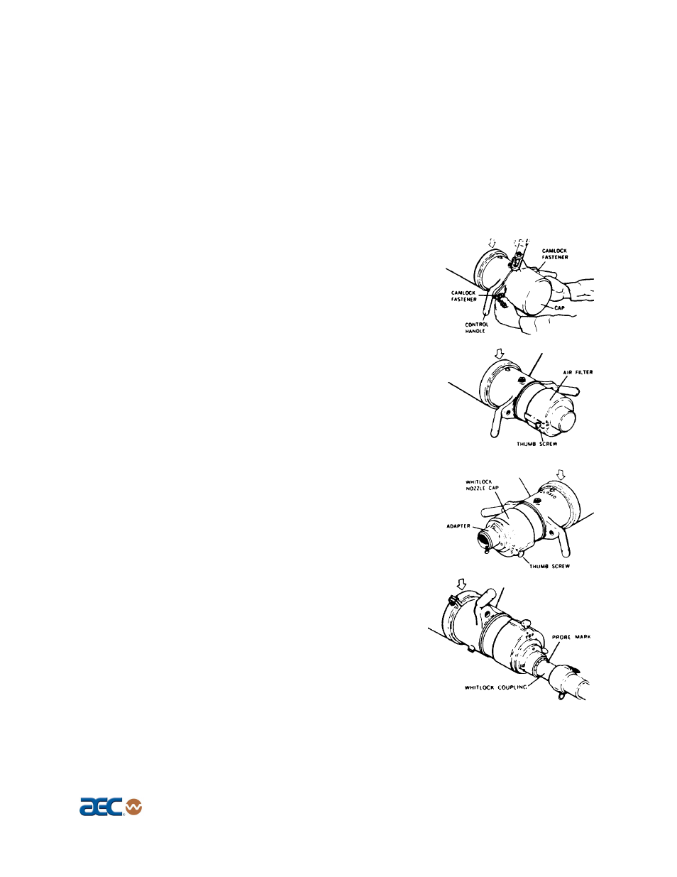
1. Open one hatch over the compartment being unloaded
(attach the hatch filter if needed).
2. Remove caps from both sides of the outlet by turning cam-
lock fasteners one quarter (¼) turn counterclockwise. Pull
the cap forward and swing out of the way.
3. With control handles in closed position (parallel to track),
place the air filter casting on the far side outlet with the
thumb screw set at 8 o’clock. Tighten the thumb screw.
4. Place the AEC nozzle cap on the unloading nozzle with
the thumb screw set at 5 o’clock. Tighten the thumb
screw.
5. Connect AEC Probe #4 (for far side unloading) to the
AEC coupling, and insert into the AEC nozzle cap as
far as it goes.
6. Set the probe mark at zero degrees. Turn the control
handle counterclockwise until the
Top
of the AEC
nozzle cap is up.