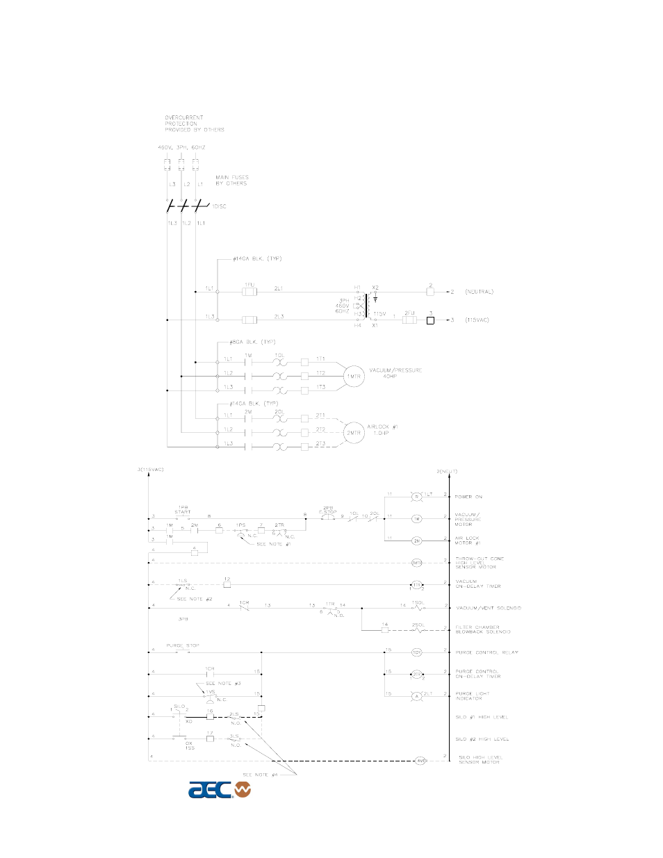
Figure 7 typical svp system electrical schematic – AEC Continuous Vacuum/Pressure Conveying Systems User Manual
Page 35
See also other documents in the category AEC Equipment:
- WD/SDA/CDA (59 pages)
- WD 350 through WD3000 Dehumidifying Dryers (84 pages)
- BCHE Mass Flow Series Drying hoppers (59 pages)
- TD Floor Mount Dryers (20 pages)
- Large AP1+ Control (100 pages)
- TD4-400-500 Floor Mount Dryer (18 pages)
- 3-Pump 33-Station Controller (52 pages)
- 1-Pump 1-Station Controller (31 pages)
- 1-Pump 9-Station Controller (39 pages)
- VacTrac Series Conveying Systems (97 pages)
- VacTrac Series Conveying Systems (120 pages)
- VacTrac Series Conveying Systems (137 pages)
- Single Conveying Units (37 pages)
- Self Cleaning Continuous Filters (41 pages)
- OFC Series (36 pages)
- OFC Series (40 pages)
- OFE Blender (35 pages)
- OFE Blender (47 pages)
- OL Series Blender (21 pages)
- OA Series Gravimetric Batch Blenders (119 pages)
- 2-40 HP Portable Chillers (79 pages)
- Glacier Series Air and Water Cooler Portable Chillers (65 pages)
- TCU Series Open Reservoir Water Temperature Control Units (51 pages)
- Econo-Cool Chillers (69 pages)
- TK Series Cooling Tower Water Treatment Systems (42 pages)
- FSS Series 1.5- 10 HP Fountain Solution Systems (81 pages)
- ACOA Series Air-Cooled Central Chillers (55 pages)
- NEC Central Station Air and Water Cooled Chiller (51 pages)
- Colortronic MA Series Auger-Feed Granulator (36 pages)
- Colortronic MODEL 253 (47 pages)
- Colortronic MS Series Screenless Granulator (43 pages)
- Colortronic MTF 3000 Series Granulator (28 pages)
- Colortronic MTF 2000 Series Granulator (39 pages)
- Colortronic MSH Series 2056 (53 pages)
- 1426-i Twin-Shear Granulator (38 pages)