AEC Continuous Vacuum/Pressure Conveying Systems User Manual
Page 29
Page 28
Single- and Dual-Blower Continuous Vacuum/Pressure Systems
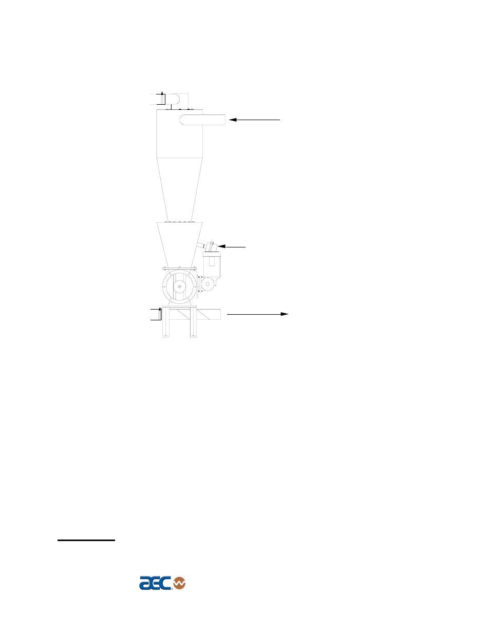
Figure 5
Rotary Airlock/Cyclone Assembly
Product from
rail car
Product
to silo
High Level Switch
(option)
9. Complete the pressure-side material line between the outlet side of the
blow-through adapter and the material destination. Connect the pressure
side material line to the blow-through adapter on the larger, square-
cornered, tapered side. See Figure 11 on Page 40 for more information.
10. Complete the material line connections from the material manifold line or
the material source to the inlet of the cyclone separator or self-cleaning
filter.
11. Complete the vacuum line connections from the vacuum unit to the filter
chamber (in pellet conveying systems) and to the cyclone separator. In a
powder conveying system, no cyclone separator or vortex filter chamber is
provided. Complete the vacuum line connections from the pump to the
outlet tube on the self-cleaning filter.
12. Check oil level in airlock gear reducer assembly.
CAUTION!
When connecting the material line, make sure it
is supported and no load is placed on the rotary airlock!