2 changing rotation direction – Watson-Marlow SPS User Manual
Page 26
MasoSine SPS sinusoidal pumps User Manual
26
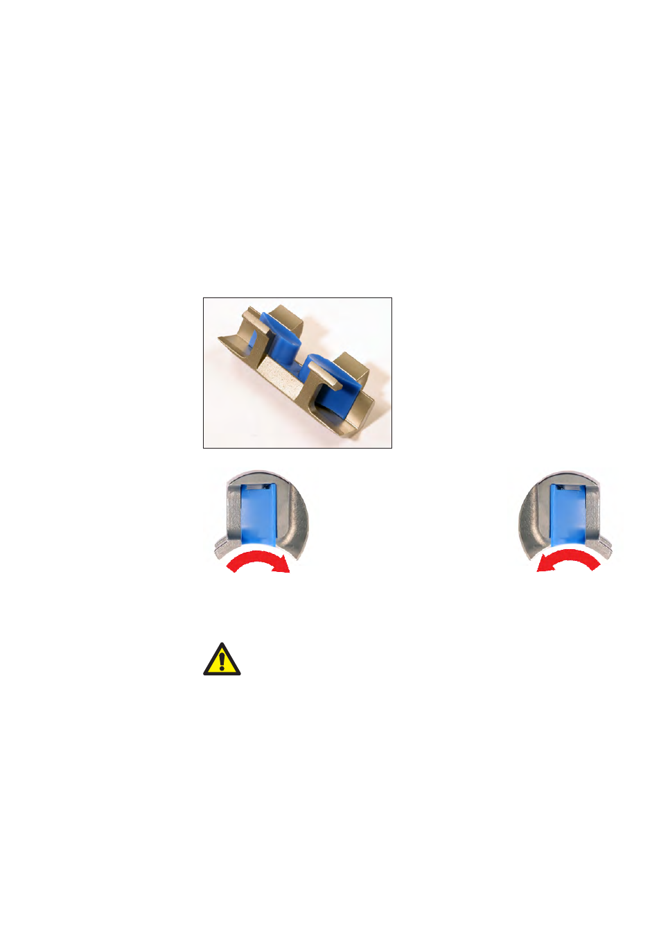
13.2 Changing rotation direction
When the direction of rotor rotation is reversed, the suction side and the pressure
side of the pump are exchanged. The orientation of the gate and the gate guide
must be changed, too, or the pump cannot pump efficiently. The pump can run for
only a short time with the gate and the gate guide wrongly oriented, and it
will not achieve more than 2 bar pressure. See 22 Dismantling and assembly.
SPS 100 is shown here. All models are similar.
Disconnect the pump from the mains power, and secure it against
unintentional start-up. Ensure that the direction change is carried
out by a trained engineer.
l Follow the dismantling and assembly steps for your pump model. See 22
Dismantling and assembly
l Take special note of the instructions for fitting the rotor, the gate and the gate
guide
Take care that fluid in the pressure line leaves the pump in an upward direction, so
that when pumping stops, some fluid remains in the pump. This will make it easier
for the pump to draw in viscous products when pumping restarts. This applies
particularly when the pressure connection is horizontal: positions 12-3 and 12-9.
Take care that the pressure line is run so that the pump rotor is always covered with
fluid, and dry running is avoided.
The gate and gate guide oriented
for clockwise rotor rotation
The gate and gate guide orient-
ed for counter- clockwise rotor
rotation
If the direction of rotation is reversed, change the rotation direction indicator arrows
and mark the suction and pressure ports correspondingly.
The gate and gate guide
shown inverted to make clear
the gate’s position within the
guide for counter- clockwise
rotor rotation