Watson-Marlow 505Du User Manual
Page 24
24
Part 3: 501RL Pumphead
Description
The 501RL pumphead has two spring-loaded working rollers, which
automatically compensate for minor variations in tubing wall thickness, giving
extended tube life.
The 501RL is set during manufacture to accept tubing with wall thicknesses of
between 1.6mm and 2.0mm, and internal diameters of up to 8.0mm. The 501RL
pumphead is equipped with a "tool lockable" guard for increased safety. This
should be locked shut whilst the pump is in use.
A major feature of the 501RL pumphead is the ability to run the pumphead
clockwise for extended tube life, or anti-clockwise to operate against higher
pressures.
The tube clamps of the 501RL are adjustable to four positions to allow varying
tube diameters to be securely held without occluding the tube.
Installation
Any one of three tubing input/output positions can be selected on cased drives.
Select the required position then fit the track over the drive shaft and locating
boss. Tighten the track retaining screw.
After checking that the shaft is clean and degreased slide the rotor on to it. The
rotor is attached to the shaft by a split collet, and it is important that the rotor
retaining screw is fully tightened to a torque of 3Nm using the largest screw
driver that will fit the screw head. This will prevent the collet slipping when the
pump is being used.
To reposition the track, remove any tubing from the pumphead, and swing out
the crank handle to expose the rotor retaining screw. Turn the screw
anticlockwise one turn to release the collet, and withdraw the rotor from the shaft.
Loosen the track locating screw, and pull the track clear. Rotate the track to its
new position and tighten the track locating screw.
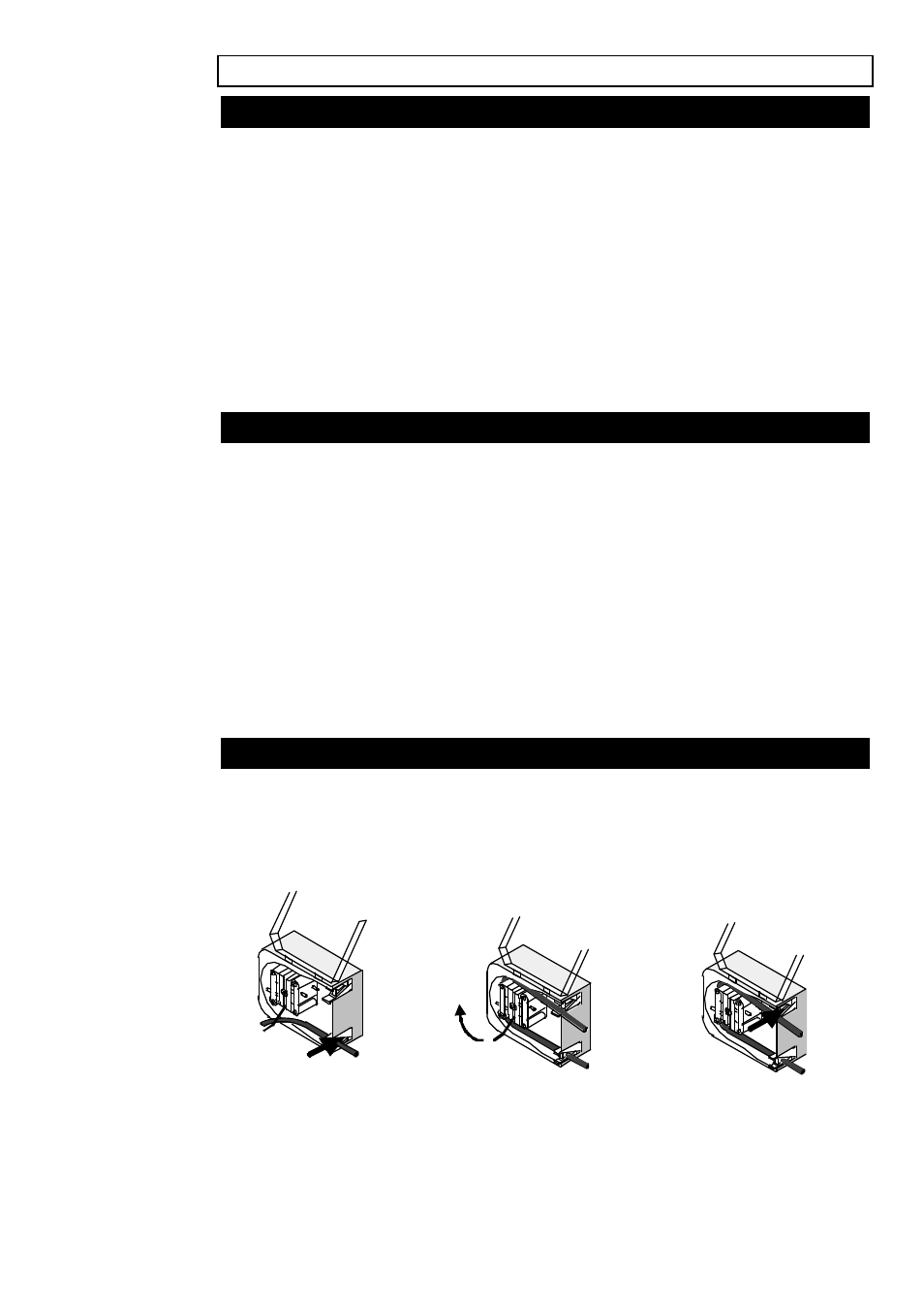
Tube loading
Switch off the drive before loading the tube. Unlock and open the hinged guard
and swing out the rotor crank handle until it locks into position.
Select the length of tubing required, noting that approximately 240mm is
required for the track system (measured from the outside faces of the tube
clamps).
Fit one end of the tubing into one of the spring loaded clamps, and then, whilst
rotating the rotor with the crank handle, feed the tubing between the rollers and
the track, aligning it within the rotor tube guides. The tubing must lie naturally
against the track and must not be twisted or stretched.