Watson-Marlow 505Du User Manual
Page 17
17
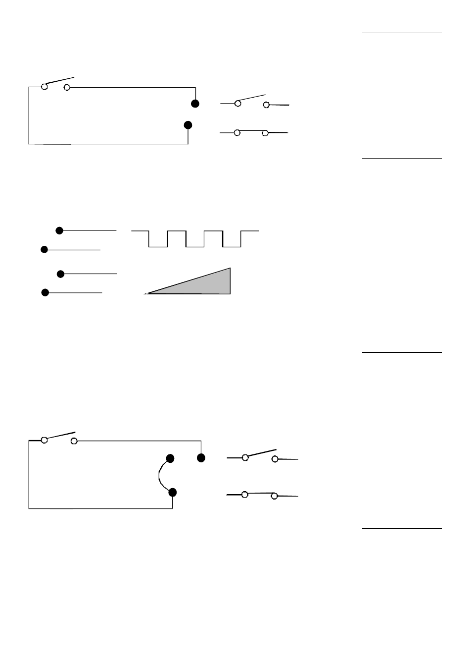
Connect remote switch between pins 7 and 16 of the 25D connector. Open
switch to run, close to stop pump. Alternatively a TTL compatible logic input (Low
0v , High 5V) may be applied to pin 7. Low input will stop the pump, High input
will allow the pump to run. With no connection the pump will default to running.
7
16
Run
Stop
This facility can be used to indicate motor speed or total the number of motor
revolutions. When using the square wave, the output is:
1280 cycles per output shaft revolution on the 220rpm drive
3200 cycles per output shaft revolution on the 55rpm drive
5V
0 to 5V dc
MAX = 5V
55 rpm 1.47 kHz
220 rpm 2.36 kHz
1
14
2
14
Connect remote switch between pins 5 and 18 and disable the front panel
reversing control by linking pins 6 and 18 of the 25D connector. Open switch for
clockwise rotation, close for counter-clockwise. Alternatively a TTL compatible
logic input (Low 0, High 5V) may be applied to pin 5. Low input will run pump in a
counter-clockwise direction, High input will run the pump in a clockwise rotation.
With no connection, the pump will default to clockwise rotation.
5
18
Anticlockwise
Clockwise
6
A remote potentiometer with a nominal value of between 1k and 5k with a
minimum of 0.25W should be wired as shown. When using a remote
potentiometer, do not apply a voltage/current control input signal at the same
time. The drive must be calibrated for 0-12V control as described in the auto
analogue section. Alternatively, the potentiometer may be used for the calibration
procedure, instead of using the minimum and maximum signals, if it is set to its
minimum and maximum positions.
Stop/start
Tachometer
Direction
Speed