Watson-Marlow 505Du User Manual
Page 13
13
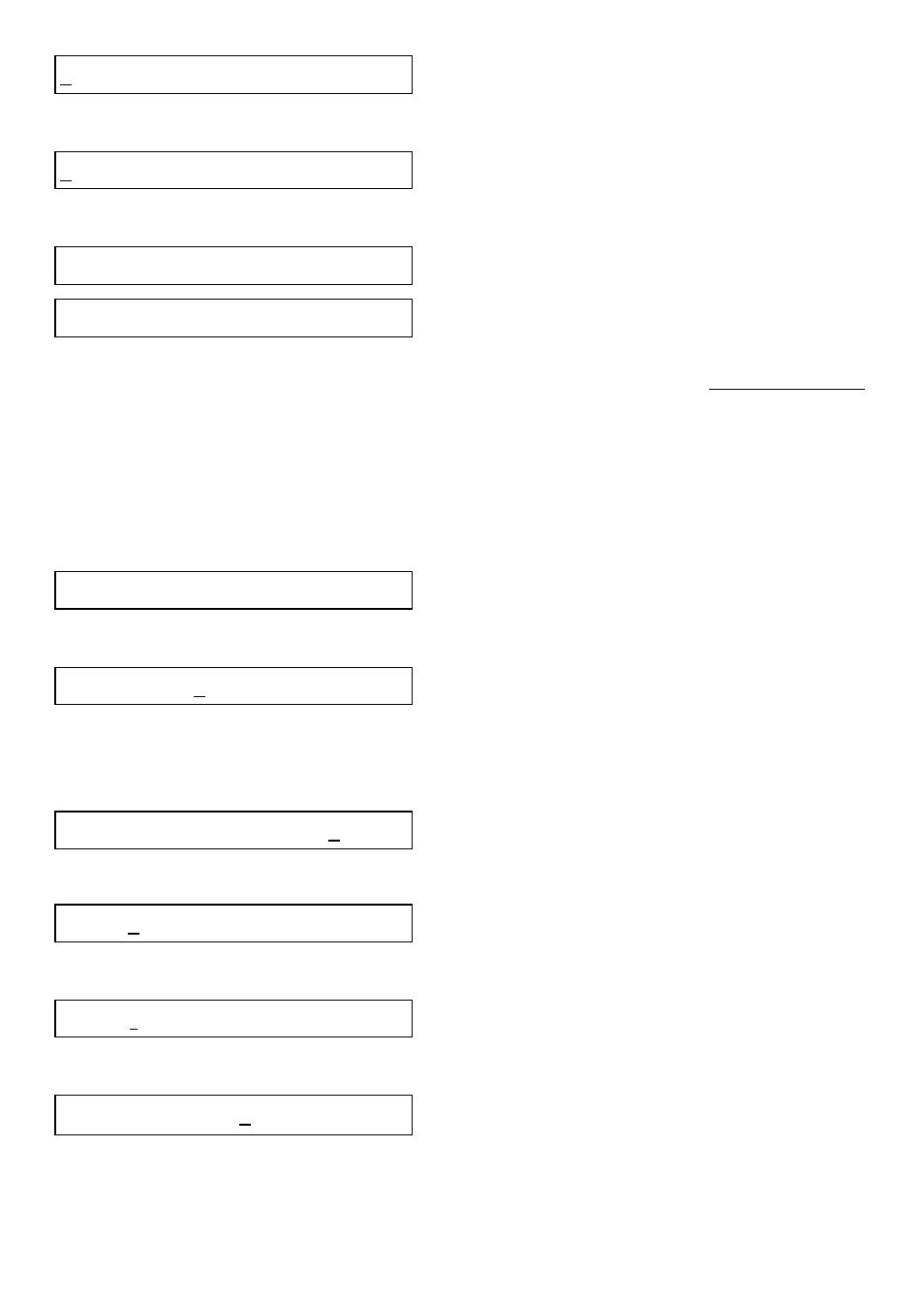
S I G N A L
P U M P - 1
Press Enter at SIGNAL
4 - 2 0 M A
0 - 1 0 M A
>
Press Enter at 4-20mA
4 - 2 0 M A
S I G N A L
=
0 - 2 2 0 R P M
R A N G E
Confirmation screens
If no signal has been chosen or programmed in SETUP, the first time AUTO is
selected, screens will prompt for signal information.
The pump will respond immediately to the process signal and the display will
initially show the parameters that have been set up, then it will display the
direction, rpm and a prompt that you are in the auto mode. If your requirement is
for a signal range or offset that is not shown, or that you require the speed to
decrease as the signal increases you must Step to SETUP on the main menu,
then Enter and Step to:
S I G N A L
P U M P - 1
>
Enter, Step, Step, Step, Step, Step
0 - 1 0 V
P R O G R A M
<
Press Enter at PROGRAM
Assume that you require the drive to run at 24rpm at 1.1V and 195rpm at 8.0V.
For a voltage signal, use the connections as shown.
S I G N A L
V
m A
Press Enter at
∨
0 . 0 V =
0 R P M
L O
Press
∧
until 1.1V is displayed. If you over-shoot, press
∨
1 . 1 V =
0 R P M
L O
Step to RPM
1 . 1 V =
0 R P M
L O
Press
∧
until 24RPM is displayed. If you over-shoot, press
∨.
Press Enter.
Note!