4 positioning of the pneumatic actuator, Positioning of the pneumatic actuator – Watson-Marlow SP40 User Manual
Page 44
MAINTENANCE OF CAM AND ACTUATORS
41
8.4
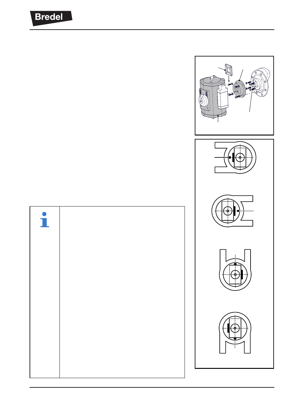
Positioning of the pneumatic actuator
In case of a pneumatic actuator first remove the dust
caps from the air connections.
Place the plastic positioning plate (A) for centring the
adaptor (B) at the bottom of the actuator (C). Use the 4
bolts and washers (D) to place the adapter onto the
actuator.
The orientation of the actuator relative to the drill mark
(M) on the bracket depends on the pump rotation and
port orientation. The drill mark (M) is always orientated
between the pump ports. The actuator is always
positioned with the air connection on the right (pump
position 2 and 3) or on the left (pump position 1 and 4).
Set the actuator in midposition by manually turning the
indicator.
C
D
B
A
Position 1
Position 3
Position 2
Position 4
M
M
M
M
The pump positions are defined as:
(pump seen from the non drive-end (NDE)
to drive-end (DE). In other words when
looking at the pump front cover.)
Position 1: ports towards the left
Position 2: ports towards the right
Position 3: ports upward
Position 4: ports downward
The actuator rotation is based on a viewing
direction from DE to NDE. Since the
actuator is mounted on the pump cover the
viewing directions for defining pump
rotation and actuator rotation are the
same.
The marks "open" and "closed" on the
actuator refer to the valve position for
which these actuators are mostly used.