V.54loop, Dtr alarm, Snmp configuration – Verilink PRISM 4101 (34-00230) Product Manual User Manual
Page 30: V.54 loop dtr alarm
18
C
HAPTER
3: F
RONT
P
ANEL
I
NTERFACE
after some delay depending on the data rate and the setting of this field. This delay
can be Normal or Long with the times shown as follows.
V.54 Loop
Selecting Enable allows the unit to respond to inband V.54 loop commands. If
Disable is selected, the unit ignores these commands.
DTR Alarm
Selecting Enable allows the unit to alarm on loss of DTR. This occurs when the
DTE port sees that the DTR signal is low. The default setting is Disable.
SNMP Configuration
The SNMP (Simple Network Management Protocol) interface is a feature of the
unit which provides seamless integration and control of CSU /DSU functions
within an existing SNMP managed LAN/WAN environment. SNMP management
stations are able to collect and analyze data from all network devices which
comply with the SNMP protocol and to manage those devices.
SNMP provides a standard means to monitor the status of all compatible network
elements. The PRISM 4101 management capabilities are expanded by the
inclusion of the TxPORT MIB and the enterprise DDS MIB. Objects in these
MIBs, and MIB loading instructions are listed in Appendix A.
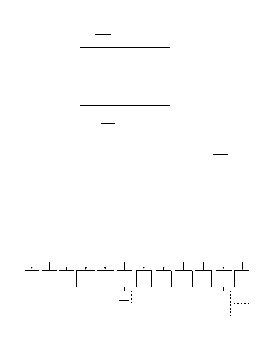
The SNMP Configuration screens are used to configure the Ethernet, SLIP, or
Token Ring SNMP interfaces. It allows for the entry of those parameters required
for proper operation of the unit with an Ethernet, SLIP, or Token Ring based LAN
manager.
Figure 3-11 SNMP Configuration Menu Structure
Table 3-2 RTS/CTS Delay Options
DDS Rate
Normal Option
Long Option
2.4 kbps
8
±
0.4 ms
16
±
0.8 ms
4.8 kbps
4
±
0.2 ms
8
±
0.4 ms
9.6 kbps
2
±
0.1 ms
4
±
0.2 ms
19.2 kbps
1
±
0.05 ms
2
±
0.1 ms
38.4 kbps
0.5
±
0.025 ms
1
±
0.05 ms
56 kbps
0.4
±
0.02 ms
0.8
±
0.04 ms
64 kbps
0.3
±
0.015 ms
0.6
±
0.03 ms
Addresses are entered as follows: An underline appears
under the digit to be changed. SCROLL increments the
digits from 0 to 9. SELECT accepts the current digit
and moves the cursor right. Press EXIT on the last digit
to enter the address and return the previous screen.
Text is entered as follows: An underline appears under the
character to be changed. SCROLL cycles through the charac-
ter set. SELECT sets the character and moves the cursor
right. Pressing EXIT on the last character enters the name
and returns the previous screen. 58 characters are allowed.
Enable
Disable
Write
Comm.
Unit
IP
Addres
Router
IP
Addres
Subnet
Mask
Filter IP
Address
1-8
Trap IP
Address
1-6
Sets
Read
Comm.
System
Contact
System
Name
System
Location
No
Yes
Reset
LAN