Verilink PRISM 3000 (34-00184) Product Manual User Manual
Page 27
Operation
3 -11
PRISM 3000
User Info/Unit ID: The idle screen top line may be
changed in this field. Text is entered using the up and down
arrow keys to scroll through each character and the right
arrow key to change cursor position. The original text can be
restored by pressing
process. The screen is shown below.
User Info / Unit ID Display Screen
NMS Address: When used with the EM8000 element man-
ager, each PRISM unit connected to the local daisy chain
must be programmed with a unique address in the range of
‘
1
’ through ‘
250
’. To program a number, scroll through the
digits with the up and down arrow key. Press the right arrow
key to select a digit. A valid NMS address must be selected
before the configuration can be recalled upon start up.
After software has been downloaded into the flash memory,
the RAM must be cleared. This process sets the NMS
address to ‘
000
’. If the unit is then powered down with this
address, it will reboot with the NMS address of ‘
251
’.
NMS Bit Rate: This field sets the interface speed for the
‘
NMS
IN
’ and ‘
NMS
OUT
’ ports. The selections are ‘
1200
’,
‘
2400
’, ‘
4800
’, ‘
9600
’, and ‘
19200
’ bps.
Supv Bit Rate: This field sets the interface speed for the
supervisory port (
SUPV
). The selections are ‘
1200
’,
‘
2400
’, ‘
4800
’, ‘
9600
’, and ‘
19200
’ bps.
Boot Mode: When the PRISM unit is powered, its config-
ured is based on this selection. If set to ‘
LOCAL
’, the unit
restores the configuration parameters in effect when power
was lost. If set to ‘
NMS
’, the unit will use the configuration
parameters supplied from the EM8000 element manager
database (the unit must have a valid NMS address - from 1
to 250). As shipped from the factory, the unit uses the fac-
tory default configurations stored in the ‘
LOCAL
’ memory.
Alarm Cutoff: When this menu item is set to ‘
DISABLE
’,
the PRISM reports a network interface alarm condition by
lighting the front panel indicator and activating the alarm
relay contacts on the rear panel. When set to ‘
ENABLE
’, the
front panel ‘
ALARM
’ indicator still lights during an alarm
condition, but the alarm contacts are forced to an inactive
state regardless of the alarm status.
Call on Alarm: This field controls remote alarm reporting.
Three submenus are available as follows:
Alarm Notification:
[
OFF
] - Disables alarm reporting.
[
DIRECT
] - Sends reports to a printer or terminal con-
nected directly to the supervisory port.
[
DIAL
] - Sends reports through an attached ‘AT’ com-
mand set compatible modem connected to the ‘SUPV’
serial port, which must dial out to a remote modem.
[
DIAL
NMS
] - Calls the EM8000 to dump alarms directly.
Edit Primary and Secondary Dial String:
These fields are 18-character ASCII strings for the call on
alarm phone numbers used in the [
DIAL
] and [
DIAL
NMS
] modes. The unit attempts 3 times to connect using
the primary number. If all 3 attempts fail, it will attempt 3
times to connect using the secondary number (if it is not
TxPORT PRISM 3000
/ =Letter
Select=Done
= move
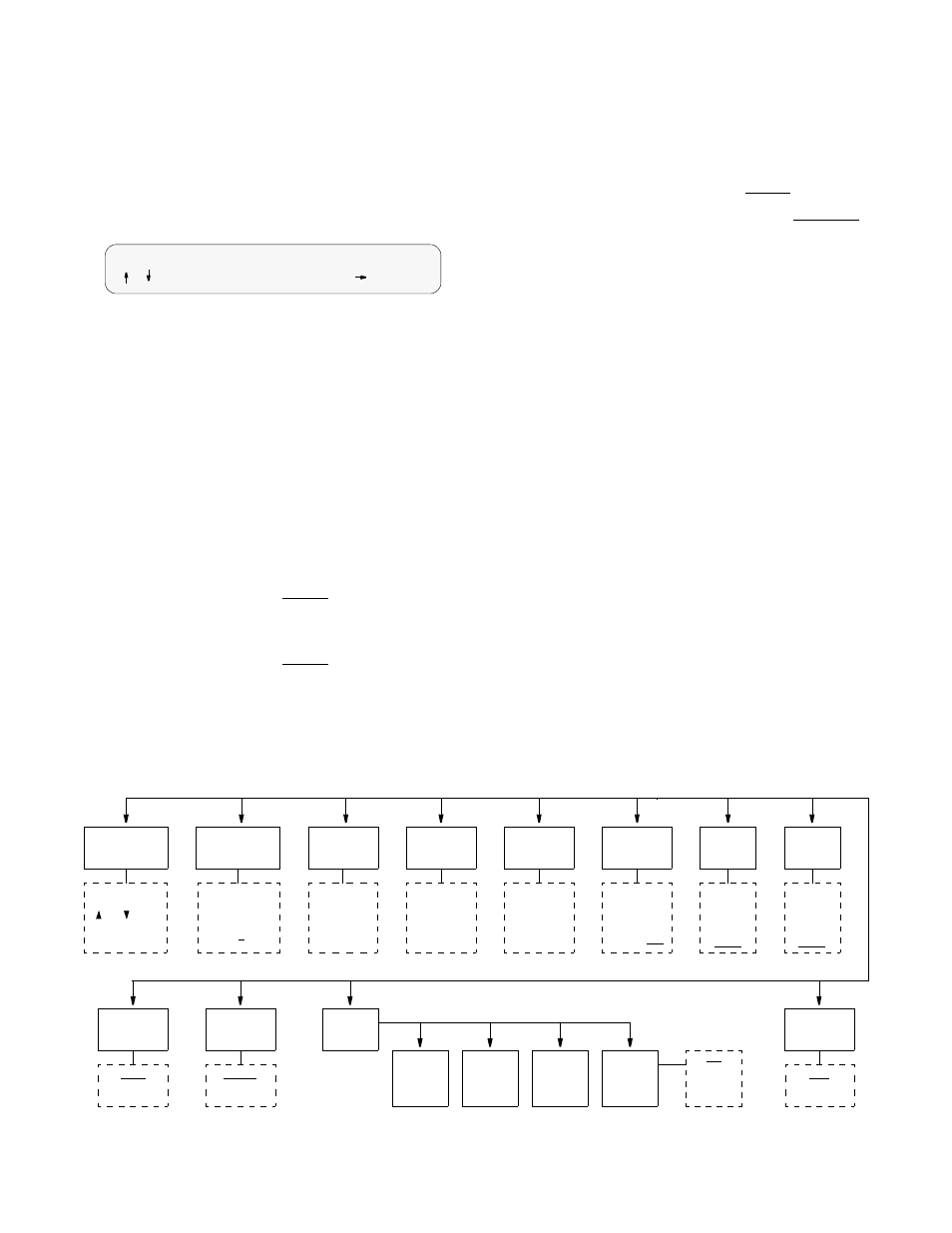
Display
View Angle
Date
Time
Edit
Password
User Info
Unit ID
Call On
Alarm
Adjusts front panel
screen contrast.
The default value
is 8.
Enter current
date in
MM:DD:YY
format.
Enter current
time in
24- hour
HH:MM:SS
format.
Enter line of
text, such as
site location,
circuit ID for
idle top line
Off
Direct
Dial
Dial NMS
Remote
Link
FDL
Ch. 1 - 24
None
NMS
Address
Enter 3 digits
in range of
1 - 250.
The default
value is 251
NMS
Bit Rate
1200
2400
4800
9600
19200
SUPV
Bit Rate
1200
2400
4800
9600
19200
Boot
Mode
Local
NMS
Alarms
Cut Off
Disable
Enable
Alarm
Notifi-
Edit
Primary
Edit
Second.
Edit
Element
Enter up to 10
characters using
and keys.
Accept and move
with right arrow.
System Utilities Menu Diagram
cation
String
String
ID