Section 3.6 – Verilink PRISM 3000 (34-00184) Product Manual User Manual
Page 23
Operation
3-7
PRISM 3000
is ON, the transmit data from the DTE is sent to the remote
end, and when RTS is OFF, idle code is sent to the remote
end. If set to ‘
Force
True
’ the CTS control lead will
always be ON and the RTS control lead from the DTE will
be ignored. Thus the transmit data from the DTE will
always be sent through to the remote end.
3.6
SNMP Configuration
The SNMP (Simple Network Management Protocol) inter-
face card is an option for the PRISM unit. It provides seam-
less integration and control of CSU/DSU functions within
an existing SNMP managed LAN/WAN environment.
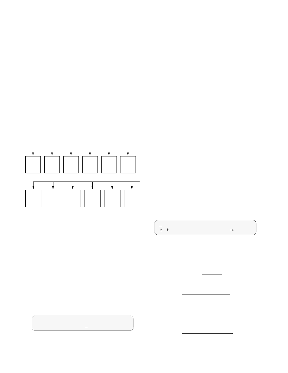
SNMP Menu Diagram
SNMP management stations are able to collect and analyze
data from all network devices which comply with the SNMP
protocol and to manage those devices. SNMP provides a
standard means to monitor the status of all compatible net-
work elements.
The ‘SNMP Configuration’ screens are accessible if the unit
is equipped with the Ethernet or Token Ring SNMP inter-
face option. It allows for the entry of those parameters
required for proper operation of the unit with an Ethernet or
Token Ring based LAN manager.
The SNMP menu consists of alpha-numeric entry only (no
selectable parameters). The following 3 menu items use the
format shown in the ‘IP Address’ screen. Each number has a
range from 0 to 255 and is separated by a period.
IP Address Screen
Unit PRISM IP Address: This field accepts IP addresses.
Each device connected to the LAN is required to have a
unique IP address identifier.
Subnet Mask: This field is provided to manually override
the subnet mask setting which is otherwise discovered by
the SNMP agent.
Router IP Address: This field accepts the IP address of a
default router, if one is present.
Filter IP Address: These eight fields accept the IP address
of the source packet filter. If any of these fields are set,
access is allowed only by the specified IP addresses.
Trap IP Address: This field accepts the IP address of a
network device where alarm reporting traps are to be sent.
The PRISM detects and reports T1 network alarms and pro-
vides several options for reporting them, one of which is
SNMP traps. When a network alarm occurs, the unit sends a
trap message to up to 6 destinations on the user’s network.
SNMP Set: This field enables or disables the set command
responses. Refer to Appendix ___ for detailed information
on these responses.
The following 5 menu items use the format shown in the
‘System Edit’ screen. The top line in each screen accepts a
string of up to 255 characters which identifies the appropri-
ate group, person, device function, or unit location. Each
character is entered using the up or down arrow keys until
the desired character is displayed. The right arrow moves
the cursor to the next position. Continue this pattern until
the last character has been selected and press
System Edit Screen
Read Community: This display accepts a character string
identifying the group authorized to perform read operations.
The default setting is ‘
public
’.
Write Community: This display accepts a character string
identifying the group authorized to perform write opera-
tions. The default setting is ‘
private
’.
System Contact: This display accepts a character string
identifying the person responsible for a network device. The
default setting is ‘
no system contact
’.
System Name: This display accepts a character string iden-
tifying the functionality of the network device. The default
setting is ‘
no system name
’.
System Location: This display accepts a character string
identifying the physical location of network device. The
default setting is ‘
no system location
’.
Unit
I P
Address
Router
IP
Address
Filter IP
Address
1 – 8
Edit
Read
Comm.
Edit
Write
Comm.
Edit
System
Contact
Edit
System
Name
Edit
System
Location
Device
Info
Subnet
Mask
Trap IP
Address
1 – 6
SNMP
Sets
SNMP Configuration
Unit IP Addrs.....132.016.232.000
<
public
/ =Letter
Select=Done
=move