R to, 10 network management – Verilink PRISM 3000 (34-00184) Product Manual User Manual
Page 14
PRISM 3000
2-4
Installation
station clock is commonly available as a 64 kHz, bipolar
RTZ signal referred to as a ‘composite clock’.
The unit will also accept any unframed all ones bipolar RTZ
signal with a level of 1.5 to 4 volts peak and a frequency of
1.544 MHz or any multiple of 56 or 64 kHz. An RS422 /423
compatible station clock input, with the same range of input
frequencies, is also available as an option.
The station timing is configured through the front panel
(refer to
Section 3.3 on page 3-3
) or through the terminal
interface (refer to
Section 4.6.1 on page 4-7
). Pin utilization
of the RJ11 (6 x4) connector is shown in the following table.
2.10 Network Management
The PRISM unit is fully compatible with TxPORT’s ele-
ment manager, the EM8000. The EM8000 software system
can be used to manage small to large networks of TxPORT
network access products.
An element is accessed by using an RS232 connection from
the serial port of the computer running the EM8000 program
to the unit’s ‘SUPV’ or the ‘NMS’ ports. The Ethernet (or
Token Ring) SNMP port in Slot 1 may also be used for net-
work management. The different connection methods are
described in the following paragraphs.
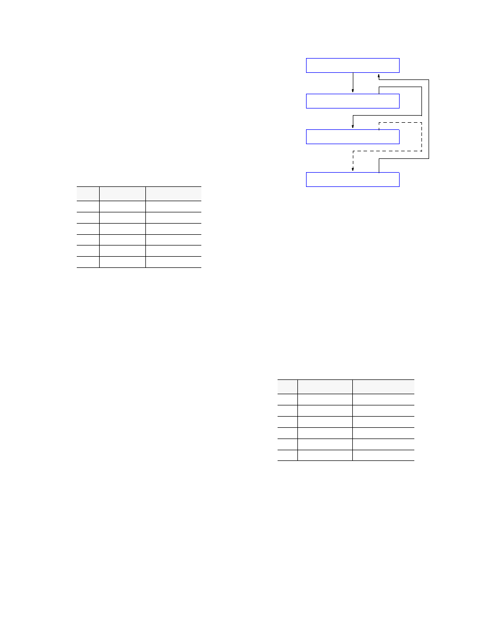
2.10.1 NMS Connection
The two 6 -pin modular connectors labeled ‘NMS IN’ and
‘NMS OUT’ on the rear panel may be used for connection
to the EM8000. This port is configured in this manner to
allow the connection of multiple collocated units in a daisy
chain IN/OUT bus arrangement as shown in
The OUT port of one element is connected to the IN port of
the next element, and so on, to form a complete chain
among the group of elements.
NOTE: All units on the same NMS chain must use the
same NMS bit rate.
Figure 2-2
NMS Daisy-Chain Arrangement
The ‘NMS IN’ connector provides both the transmit and
receive signal pair. This port may be used for a modem con-
nection or as a VT100 terminal interface (refer to the ‘Ter-
minal Operation’ chapter).
The EM8000 may be connected directly into the NMS chain
between two elements if connection to the ‘SUPV’ port is
not desirable. A ‘Y’ cable is used from the EM8000 serial
port which splits the transmit and receive signals into two 6-
pin modular connectors for the ‘NMS IN’ and ‘NMS OUT’
ports. See
Section 1.6 on page 1-5
for ordering information.
The NMS address, NMS bit rate, and boot configuration
mode is set by the front control panel as described in
Sec-
tion 3.8 on page 3 -10
. The physical connection of the NMS
port is a 6-pin modular connector with the pinout shown in
the following table. This is a serial RS232 DCE port config-
ured for 8 bits, no parity, and 1 stop bit.
2.10.2 Supervisory Port Connection
The rear panel ‘SUPV’ port serves several functions. The
terminal interface program may be accessed through this
port (refer to
). A modem may be
connected to this port for remote access or use of the call on
alarm feature (refer to
).
For cabling convenience, The EM8000 workstation may be
directly connected to the supervisory port. When a group of
Pin
TTL Signal
Bipolar Signal
1
Ground
Ground
2
Not Used
Not Used
3
TTL Clock
Balanced Tip
4
Ground
Balanced Ring
5
Not Used
Not Used
6
Ground
Ground
Pin
NMS BUS IN
NMS BUS OUT
1
Not Used
Not Used
2
Signal Ground
Signal Ground
3
Data Out
Data Out
4
Data In
Not Used
5
Signal Ground
Signal Ground
6
Not Used
Not Used
IN
OUT
NMS
IN
OUT
NMS
Element #1
Element #2
OUT
IN
NMS
EM8000
IN
OUT
NMS
Last Element