Section 3.8, 8 system utilities – Verilink PRISM 3000 (34-00184) Product Manual User Manual
Page 26
PRISM 3000
3-10
Operation
recorded by interval. Counting will stop when the maxi-
mum value of 65535 is reached.
Clear ESF Stats: When ‘
YES
’ is selected, all user net-
work performance registers are set to zero and the param-
eter returns to ‘
NO
’. The telco register set (accessible by
the service provider) is not cleared by this action.
Network Alarms: The network interface alarm status is
reported as one of the states shown in the following para-
graphs. The front panel alarm indicator and the rear panel
alarm relay contacts are controlled solely by the user
selected ‘Alarm Thresholds’ set in the ‘T1 NET Configura-
tion’ menu (see
).
SIGNAL LOSS: Indicates that the T1 receive signal level
has dropped below the level that can be detected.
SYNC LOSS: Indicates that the unit is unable to synchro-
nize on the incoming T1 framing pattern.
AIS: Indicates that an unframed ‘all ones’ pattern is being
received.
YELLOW/REMOTE: Indicates that a remote (yellow)
alarm indication is being received.
T1 DTE Alarms: T1 DTE alarm status is reported using
the same parameters as defined for ‘
Network
Alarms
’ in
the preceding paragraphs. The front panel alarm indicator
and the rear panel alarm relay contacts are a function of the
network alarm thresholds, not the T1 DTE interface.
3.8
System Utilities
The System Utilities display allows the user to perform the
various functions described in the following paragraphs.
System Utilities Screen
Edit Password: The PRISM is factory shipped with the
password disabled (factory default). A password is selected
by entering up to 10 alphanumeric characters. Each charac-
ter is entered using the up or down arrow keys until the
desired character is displayed. The right arrow moves the
cursor to the next position. Continue this pattern until the
last character is selected and then press
NOTE: The password is case sensitive. During log on,
it must be entered exactly as it was programmed.
Display View Angle: The contrast of the front panel LCD
display will have a different appearance depending on
whether it is being viewed from a high angle or a low angle.
Use the arrow keys to adjust for the most suitable contrast.
There are 18 selectable values, with a default value of ‘
8
’.
Time: The current time is set by entering each digit in the
standard 24-hour ‘
HH:MM:SS
’ format. Each field is range
checked and automatically limited to the appropriate range
of values.
Date: The current date is set by entering each digit in the
standard ‘
MM/DD/YY
’ date format. Each field is range
checked and automatically limited to the appropriate range
of values.
System Utilities
> Edit Password
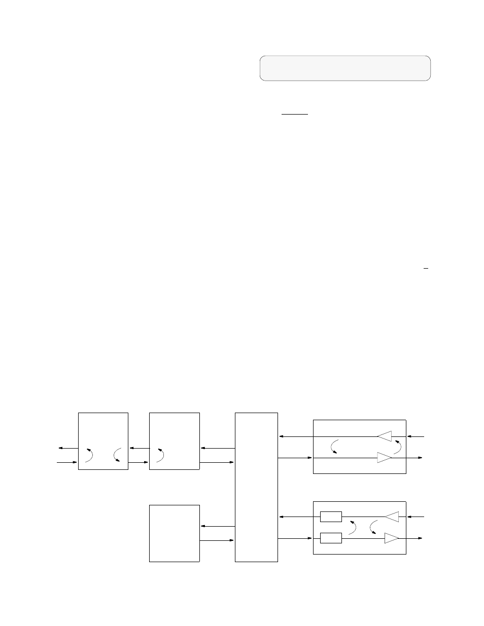
Multiplexor
BERT
Pattern
Generator
and
Detector
Framing,
CRC, & FDL
Control
Network
Interface
Tx
Rx
DSX1 T1 DTE Port
Receiver
Driver
TX
RXD
DTE Slot X, Port Y
Receiver
Driver
TXD
RXD
FIFO
FIFO
NET LLB
NOTE: Commanded loops are
initiated by receipt of the appro-
priate loop code from the net-
work or the far end CSU/DSU.
Bidirectional fractional port loop
DTE MLB
NET PLB
DTE LLB
NET MLB
Diagnostics Loop Functions